Device and method for processing molten metals with ultrasound waves

A metal melt and ultrasonic technology, applied in the direction of improving process efficiency, etc., can solve the problems of high temperature resistance and corrosion resistance, serious ultrasonic attenuation, brittle fracture of assembly, etc., and achieve low cost, simple device and method Effect

Active Publication Date: 2013-01-16
TSINGHUA UNIV
View PDF4 Cites 4 Cited by
  • Summary
  • Abstract
  • Description
  • Claims
  • Application Information

AI Technical Summary

Problems solved by technology

[0003] The existing research method is mainly to immerse the ultrasonic tool rod in the metal melt to be treated for ultrasonic treatment, but when this method is used to treat high melting point metals (such as steel melt), the high temperature resistance and corrosion resistance of the ultrasonic tool rod The performance requirements are high, and traditional metal materials are difficult to meet the requirements; eve

Method used


Image

  • Device and method for processing molten metals with ultrasound waves

Examples


Embodiment 1

[0034] Embodiment 1: Device structure for ultrasonic treatment of molten metal

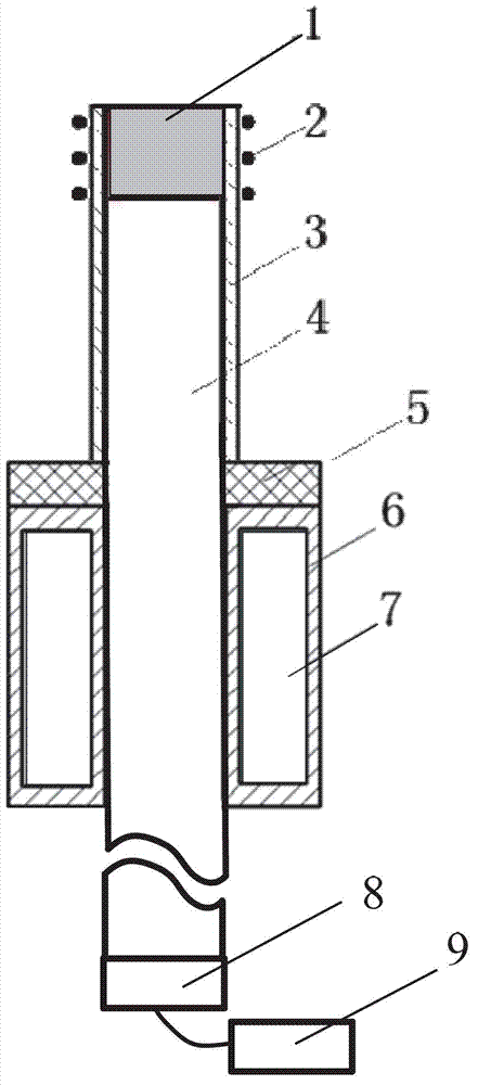
[0035] Such as figure 1 As shown, the structure of the device utilizing ultrasonic treatment of molten metal according to the present invention is as follows:

[0036] The metal 1 to be treated and the ultrasonic tool bar 4 are integrated rods with the same diameter, and the two are connected together by welding or casting; and the metal 1 to be treated is located at the top of the ultrasonic tool bar 4; the ultrasonic tool bar 4 The length of the ultrasonic wave is an integer multiple of the half-wavelength that the ultrasonic wave propagates in the metal material used in the ultrasonic tool bar 4; the length of the metal 1 to be processed is 0.5 to 3 times its diameter;

[0037] The metal 1 to be treated and the upper part of the ultrasonic tool bar 4 are encased by a quartz tube 3; the melting point of the quartz tube 3 is higher than the melting point of the metal 1 to be treated; the wall th...

Embodiment 2

[0041] Embodiment 2: Utilize the device for ultrasonic treatment of molten metal to process molten metal method

[0042] Such as figure 1 Shown, utilize the device of ultrasonic treatment metal melt of the present invention to process metal melt method as follows:

[0043] (1) Select the same material as the metal 1 to be processed to make the ultrasonic tool rod 4, wherein the metal 1 to be processed is located at the top of the ultrasonic tool rod 4, and the ultrasonic tool rod 4 and the metal 1 to be processed are directly melted or welded on the Together; wherein, the length of the ultrasonic tool bar 4 is 1 time of the half-wavelength that ultrasonic waves propagate in the tool bar material, and the length of the metal 1 to be processed is 1 time of the metal diameter to be processed; the ultrasonic tool bar 4 is placed vertically , so that one end of the metal 1 to be processed is upward;

[0044] (2) Select a quartz material with a higher melting point than the metal ...


PUM


Abstract

The invention discloses a device and a method for processing molten metals with ultrasound waves, belonging to the technical field of molten metal treatment. Metals to be processed and ultrasonic tool rods are integrated rods with the same diameter; quartz tubes are sleeved the upper portions of the metals to be processed and the ultrasonic tool rods; heating devices are arranged on peripheries of the quartz tubes; the lower portions of the ultrasonic tool rods are sleeved with water cooling sleeves; the quartz tubes are separated from the water cooling sleeves by insulation cottons; ultrasonic transducer and ultrasonic controllers are connected below the ultrasonic tool rods. The heating devices start when using; inert gas is led on the top ends of the metals to be processed to protect; cooled water is led into the water cooling sleeves; the heating devices start again to melt the metals to be processed to form a molten metal tank; the ultrasonic transducer and ultrasonic controllers start; the frequency of the ultrasound waves are regulated to make the ultrasonic tool rods and the molten metal tank resonate and process the molten metals to be processed. The device and the method have the advantages of convenience, low cost, no loss of ultrasonic energy and wide use.

Description

technical field [0001] The invention belongs to the technical field of metal melt treatment, in particular to a device and method for treating metal melt with ultrasonic waves. Background technique [0002] The quality of metal products such as ingots, castings, and continuous casting products is directly determined by the quality of the smelting process and the metal melt (such as molten steel). The control level of gases and inclusions in the melt is an important reflection of the purity of the metal melt. With the continuous development of smelting technology and equipment, the purity of molten steel has been greatly improved, and the level of inclusions and gas content has been reduced, but this problem still exists. Ultrasonic treatment of metal melts can refine the solidified grains of metals, promote the formation of gas bubbles in the metal melts and grow up to float, and can promote the agglomeration of inclusions and then float up. Some studies also believe that i...

Claims


Application Information

Patent Timeline
IPC IPC(8): C22B9/02B22D27/08
CPCY02P10/20
Inventor 康进武聂刚游锐胡毅森
Owner TSINGHUA UNIV
Why Eureka
Try Eureka