Production process of copolymer for semiconductor lithography

Active Publication Date: 2005-05-05
MARUZEN PETROCHEMICAL CO LTD
View PDF4 Cites 8 Cited by
  • Summary
  • Abstract
  • Description
  • Claims
  • Application Information

AI Technical Summary

Benefits of technology

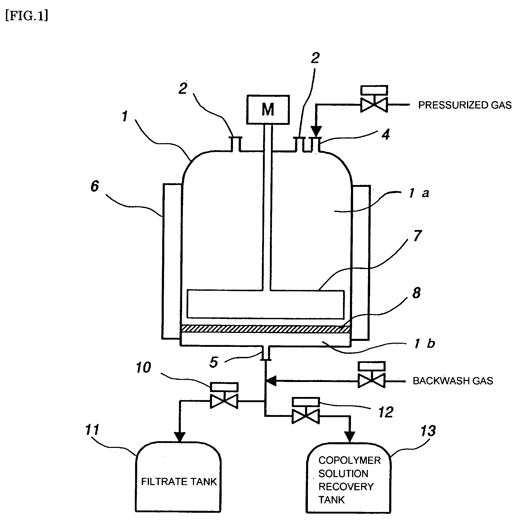
[0022] In each filtration step, the filtration can preferably be conducted while agitating contents with an impeller, and/or a resulting filter cake of the solid can preferably be spread with the impeller, for example, by reciprocating the impeller up and down, and/or in the course of each filtration step, one of the filtrated solvent or a gas can preferably be caused to flow backward from the second section of the vessel into the first section of the vessel such that any deposit on the filter medium is separated from the filter medium. The filtration can be efficiently performed by conducting it as described above.
[0023] According to the present invention, the precipitation and filtration steps and/or the washing and filtration steps can be performed in the single vessel. It is, therefore, unnecessary to transfer a precipitation mixture or washing mixture to a filter tank or to transfer a filter cake to a washing tank or the like. This makes it possible to avoid contamination from the outside and also

Problems solved by technology

If unreacted monomers, polymerization initiators, chain transfer agents, their coupling products or the like, or impurities added or formed upon polymerization reactions remain in copolymers for semiconductor lithography such as these resist polymers and polymers for anti-reflective coatings, they may evaporate and damage aligners in lithography, or during storage as copolymers or in the form of compositions for lithography, they may undergo polymerization to form substances that may cause pattern defects.
This method is, however, accompanied by a problem that impurities such as unreacted monomers cannot be fully eliminated when precipitation is conducted only once.
The methods in which a solid is dispersed in a solvent and then heated are, however, accompanied by a problem that a portion of the resulting copolymer is dissolved into the solvent and the yield of the copolymer is lowered.
These operations involve problems that they are irksome, require many equipment, are inefficient, and further, are vulnerable to contamination from the outside.
With a conventional filter apparatus, the resulti

Method used


Image

  • Production process of copolymer for semiconductor lithography

Examples


Example

Example 1

[0085] Methyl ethyl ketone (hereinafter abbreviated as “MEK”) (68 kg), 5-methacryloyloxy-2,6-norbornanecarbolactone (hereinafter abbreviated as “NLM”) (16 kg) and 2-methyl-2-adamantyl methacrylate (hereinafter abbreviated as “MAM”) (19 kg) were charged in a nitrogen-purged, feed preparation tank, and were then agitated at 20 to 25° C. to prepare a monomer solution. MEK (3 kg) and dimethyl-2,2′-azobisisobutyrate (0.6 kg) were charged in a nitrogen-purged polyethylene tank, and were then agitated at 10 to 20° C. to dissolve them into an initiator solution. Further, MEK (35 kg) was charged in a nitrogen-purged polymerization tank and then heated to 80° C. under agitating. The monomer solution and initiator solution, which had been prepared beforehand, were then fed separately at constant rates over 4 hours into the polymerization tank. An aging reaction was conducted for 2 hours while maintaining the polymerization tank at 80° C. even after the completion of the feeding. The ...

Example

Example 2

[0091] The procedures of Example 1 were repeated likewise except that in each of the precipitation and filtration steps and the washing and filtration steps, the temperature of methanol was maintained at 5° C. and the temperature was controlled at 3 to 6° C. The results are presented in Table 1.

Example

Example 3

[0092] The procedures of Example 1 were repeated likewise except that in each of the precipitation and filtration steps and the washing and filtration steps, the temperature of methanol was maintained at 30° C. and the temperature was controlled at 28 to 31° C. The results are presented in Table 1.

Referential Example 1

[0093] The procedures of Example 1 were repeated likewise except that in each of the precipitation and filtration steps and the washing and filtration steps, the filtration was conducted without causing nitrogen gas to flow backward. The results are presented in Table 1.

Referential Example 2

[0094] The procedures of Example 1 were repeated likewise except that in each filtration, spreading of a filter cake was not conducted. The results are presented in Table 1.

Referential Example 3

[0095] The procedures of Example 1 were repeated likewise except that in each filtration, neither agitating of a slurry nor spreading of a filter cake was conducted. The resul...


PUM

PropertyMeasurementUnit
Temperatureaaaaaaaaaa
Pore sizeaaaaaaaaaa

Abstract

Efficient and reproducible production of a copolymer for lithography, which has stable quality, with little lot-to-lot variations, and is suited for film-forming and coating compositions. Radical polymerization of a monomer, which contains at least one ethylenic double bond, with an initiator, in a solvent, and purification of the reaction mixture by precipitation and filtration, in a hermetically-closable single vessel divided by a filter medium, into a first section provided with fluid feeding means and agitating means, and a second section with fluid drawing means. Feeding the reaction mixture from the fluid feeding means into the first section of the vessel, containing a poor solvent, and contacting the reaction mixture with the poor solvent to precipitate a solid; and filtering the resulting fluid, containing the precipitated solid, through the filter medium, drawing the resultant filtrate through the fluid drawing means, and then separating the precipitated solid.

Description

FIELD OF THE INVENTION [0001] This invention relates to a process of producing a copolymer for semiconductor lithography, which is suited as a film-forming polymer in semiconductor lithography such as a polymer for resists, a polymer for anti-reflective coatings, and a polymer for under layers in multilayer resists, and more specifically, to a process for producing a copolymer for semiconductor lithography by radical polymerization, which comprises causing the copolymer, which has been obtained by the radical polymerization, to precipitate in a poor solvent, and then washing and separating the precipitate. DESCRIPTION OF THE BACKGROUND [0002] In lithography for the fabrication of semiconductors, the formation of finer patterns is required in step with increases in the degree of integration. For further reductions in pattern size, wavelength shortening of exposure light sources is indispensable. At present, lithography by krypton fluoride (KrF) excimer laser (wavelength: 248 nm) is b...

Claims


Application Information

Patent Timeline
IPC IPC(8): C08F6/00C08F6/12C08F118/02C08F220/06G03F7/004G03F7/039G03F7/09
CPCC08F6/12G03F7/0392G03F7/094G03F7/091G03F7/0397G03F7/0045
Inventor YAMAGISHI, TAKANORIKATO, ICHIROYAMAGUCHI, SATOSHI
Owner MARUZEN PETROCHEMICAL CO LTD
Why Eureka
Try Eureka