Two-stroke engine

a two-stroke engine and engine technology, applied in the direction of combustion engines, combustion air/fuel air treatment, combustion feed systems, etc., can solve the problems that the sealing of the air channel can only be achieved with a large complexity of a substantially closed throttle flap, and achieve the sealing of the air channel downstream of the throttle flap. , the effect of increasing the pressure level and increasing the pressure level in the intake channel

Inactive Publication Date: 2005-05-12
ANDREAS STIHL AG & CO KG
View PDF6 Cites 5 Cited by
  • Summary
  • Abstract
  • Description
  • Claims
  • Application Information

AI Technical Summary

Benefits of technology

[0004] It is an object of the invention to provide a two-stroke engine of the kind described wherein a favorable ratio of air and fuel can be made available with little complexity in each operating state.
[0006] A higher pressure is present in the crankcase than in the air channel closed by the throttle element in a region between approximately 90° ahead of bottom dead center and up to 90° after bottom dead center of the piston. A pressure compensation can take place between the air channel and the crankcase via the connection between the air channel and the crankcase. No ambient air is any longer drawn in by suction because the pressure level in the air channel downstream of the throttle flap is increased. A leaning of the mixture because of the additionally inducted and substantially fuel-free air into the air channel can be avoided in this way in a simple manner. An increase of the pressure level can be realized also via the connection between the crankcase and the intake channel. The pressure level in the intake channel is increased via the connection when the inlet of the intake channel is closed. For this reason, less fresh gas flows through the carburetor into the intake channel in this phase. In order to ensure the required charge of the intake channel, the throttle flap can be opened further in the intake channel. In this way, the requirements as to seal tightness on the throttle flap in the intake channel and on the throttle element in the air channel are reduced.
[0007] The connection advantageously is present at bottom dead center of the piston. It is practical that the connection between the supply channel and the crankcase is present at each position of the piston. However, it can be practical that the connection is controlled in dependence upon the position of the piston. A simple configuration results when the connection is slot controlled via the piston. In this way, it can be ensured that the connection is present only in a range of approximately between 90° ahead of bottom dead center and 90° after bottom dead center.
[0008] The connection is controlled via at least one valve. The connection is controlled in dependence upon the engine load. In this way, it can be ensured that the connection is only present at idle or at low loads. In these cases, the throttle element is substantially closed. At high engine loads, the throttle element is substantially opened so that an underpressure compensation is not necessary. The position of the valve is especially controlled in dependence upon the position of the throttle element. However, it can be practical that the connection is present independently of the engine load. The connection is advantageously configured in a connecting channel. The connecting channel opens at the cylinder bore and the opening is connected to the crankcase via a piston window in the piston in the region of bottom dead center.
[0009] The flow cross section in the connecting channel is at most a third of the flow cross section in the intake channel. In this way, it is ensured that only a pressure compensation is achieved via the connecting channel. Essential mass flows in the connecting channel can thereby be avoided. A throttle is mounted in the connecting channel in order to compensate for pressure fluctuations in the connecting channel. The connection is advantageously configured as a slot in the cylinder wall. In this way, a simple configuration of the connection results.

Problems solved by technology

A reliable sealing of the air channel can be achieved only with great complexity for a throttle flap which is substantially closed.

Method used


Image

  • Two-stroke engine
  • Two-stroke engine
  • Two-stroke engine

Examples


Embodiment Construction

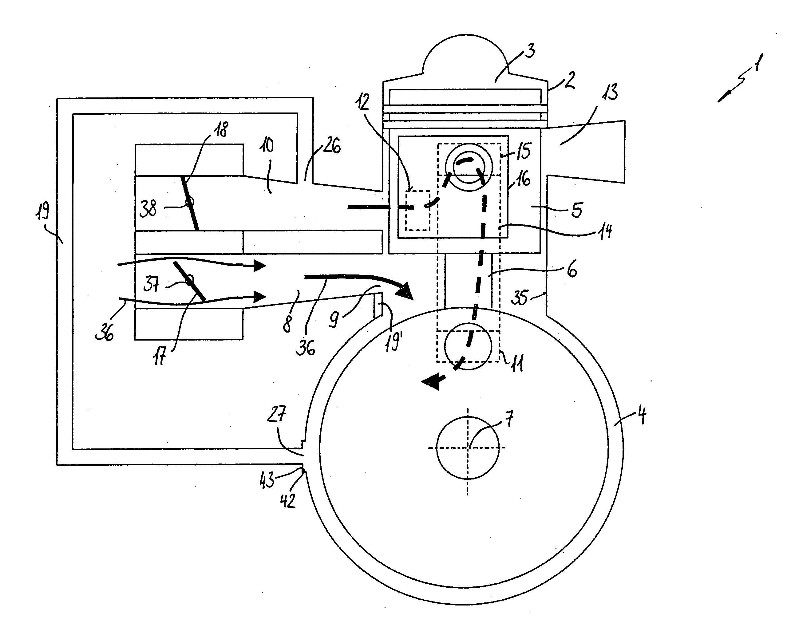
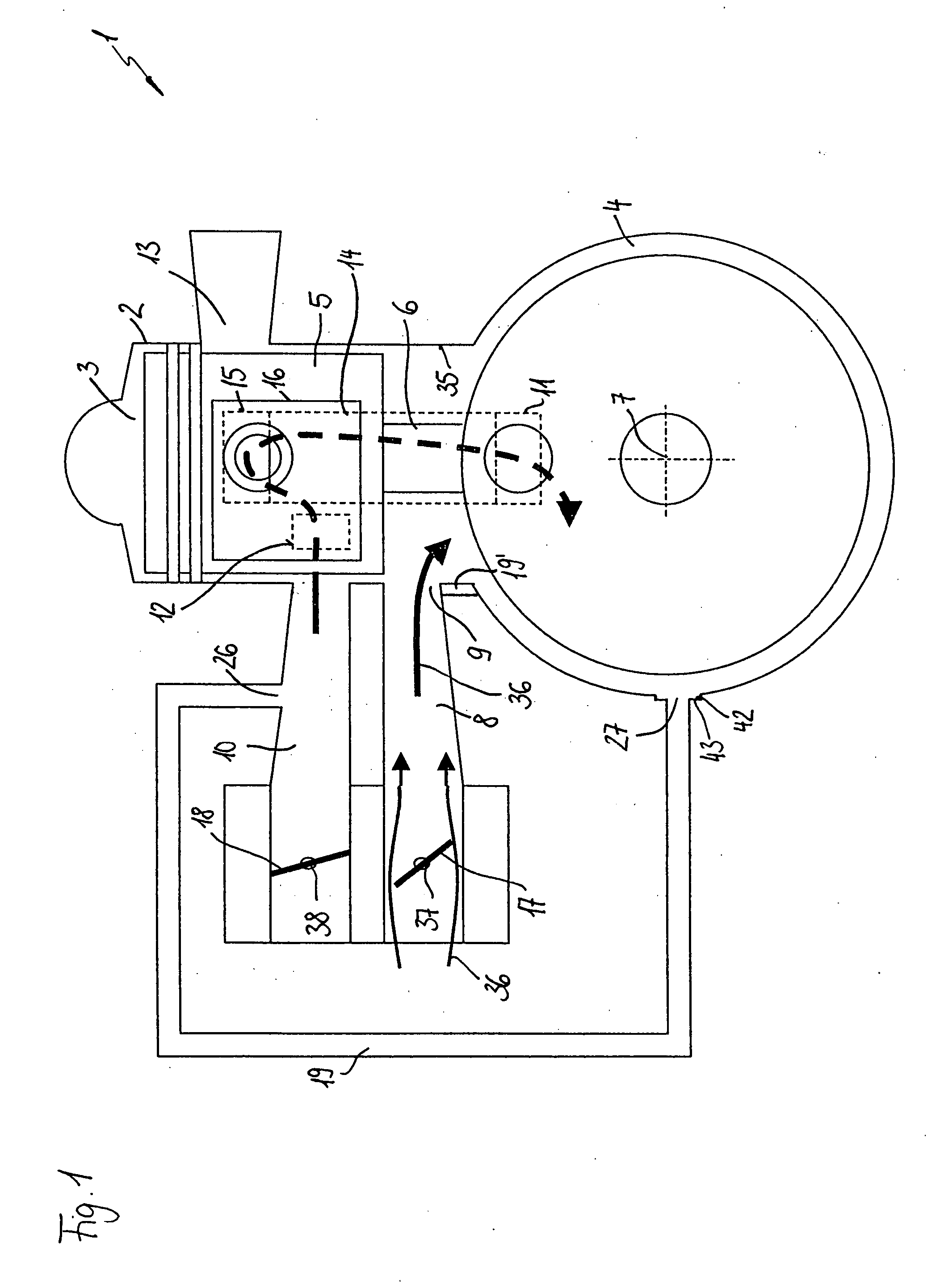
[0016] The two-stroke engine 1 shown in FIG. 1 includes a cylinder 2 wherein a combustion chamber 3 is formed. The combustion chamber 3 is delimited by a piston 5. The piston 5 is journalled in the cylinder 2 so as to be displaceable in the longitudinal direction. The piston 5 rotatingly drives a crankshaft 7 via the connecting rod 6 and the crankshaft 7 is rotatably journalled in the crankcase 4. The two-stroke engine 1 includes an intake channel 8 which opens with an inlet 9 at the cylinder bore 35. The inlet 9 of the intake channel 8 is slot controlled by the piston 5. In the intake channel 8, a throttle flap 17 is pivotally journalled about a throttle shaft 37. The throttle flap 17 can be mounted in a carburetor wherein an air / fuel mixture is prepared. In dependence upon the position of the throttle flap 17, an air / fuel mixture flows in the direction of arrows 36 through the intake channel 8 and into the crankcase 4 as long as the inlet 9 is cleared by the piston 5.

[0017] An ai...


PUM


Abstract

A two-stroke engine (1) has a combustion chamber (3) disposed in a cylinder (2). The combustion chamber (3) is delimited by a reciprocating piston (5). The piston (5) drives a crankshaft (7) via a connecting rod (6) and the crankshaft (7) is rotatably journalled in a crankcase (4). The two-stroke engine (1) has an intake channel (8) for the supply of fuel into the crankcase (4), an outlet (13) for exhaust gases from the combustion chamber (3) and an air channel (10) for the supply of substantially fuel-free air. A throttle element (18) is mounted in the air channel (10). At pregiven positions of the piston (5), the crankcase (4) is connected via at least one transfer channel (14) to the combustion chamber (3). In order to prevent air from being drawn by suction into the air channel because of leakages during idle or at low rpm, a fluid connection is provided between the air channel (10) downstream of the throttle element (18) and the crankcase (4) for underpressure compensation which connection is present at least partially for a position of the piston from 90° ahead of bottom dead center to 90° after bottom dead center. A connection between the crankcase (4) and the intake channel (8) can be provided in lieu of, or in addition to, the connection to the air channel (10).

Description

CROSS REFERENCE TO RELATED APPLICATION [0001] This application claims priority of German patent application no. 103 52 808.3, filed Nov. 12, 2003, the entire content of which is incorporated herein by reference. FIELD OF THE INVENTION [0002] The invention relates to a two-stroke engine including a two-stroke engine in a portable handheld work apparatus such as a motor-driven chain saw, cutoff machine or the like. BACKGROUND OF THE INVENTION [0003] U.S. Pat. No. 6,712,029 discloses a two-stroke engine wherein substantially fuel-free air is supplied from an air channel to the transfer channels via a piston window. In the air channel, a throttle flap is provided for controlling the supplied air quantity. The throttle flap is completely or at least substantially closed during idle and during low engine load. An underpressure is formed in the air channel section downstream of the throttle flap because of the substantially closed throttle flap. The underpressure causes ambient air or air ...

Claims


Application Information

Patent Timeline
Patent Type & Authority Applications(United States)
IPC IPC(8): F02B25/20F02B33/04F02B63/02F02B75/02F02D9/02F02M35/108
CPCF02B25/20F02B33/04F02B63/02F02M35/108F02D9/109F02D2009/0279F02M35/1019F02B2075/025
Inventor LINGEN, ANDREASHEHNKE, MATTHIASBAUMHAUER, JOACHIMBAHNER, ANDREASJOOS, MICHAELKLIMMEK, AXELHOLDERLE, HANS
Owner ANDREAS STIHL AG & CO KG
Why Eureka
Try Eureka