Focusable and steerable micro-miniature x-ray apparatus

a x-ray apparatus and micro-miniature technology, applied in the field of micro-miniature x-ray apparatuses, can solve the problems of not focusing and steering the output of sources, and achieve the effect of sufficiently inexpensive fabrication

Active Publication Date: 2005-05-19
LUCENT TECH INC
View PDF16 Cites 101 Cited by
  • Summary
  • Abstract
  • Description
  • Claims
  • Application Information

AI Technical Summary

Benefits of technology

[0013] Advantageously, our x-ray source, including its focusing, collimating and steering components, can be fabricated small enough to be mo...

Problems solved by technology

The output of the sources is not focused and is not steered, which is undesirable to t...

Method used


Image

  • Focusable and steerable micro-miniature x-ray apparatus
  • Focusable and steerable micro-miniature x-ray apparatus
  • Focusable and steerable micro-miniature x-ray apparatus

Examples


Embodiment Construction

General Structure

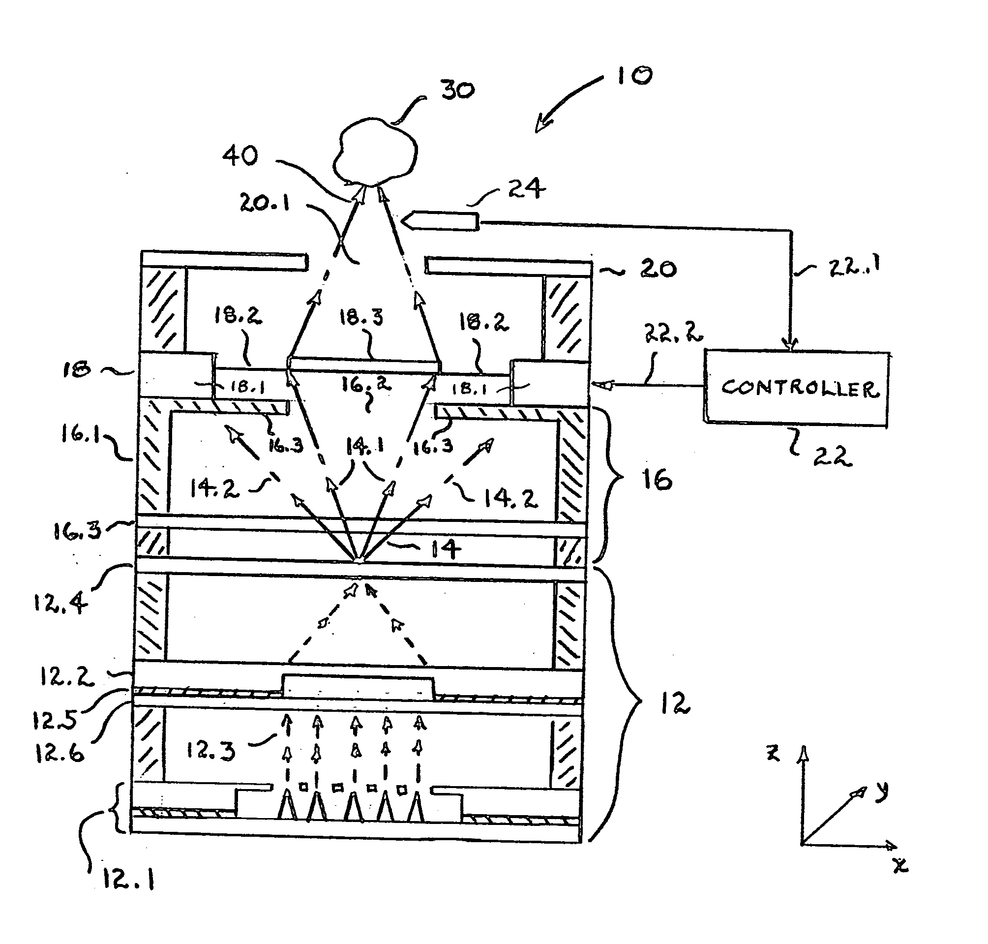
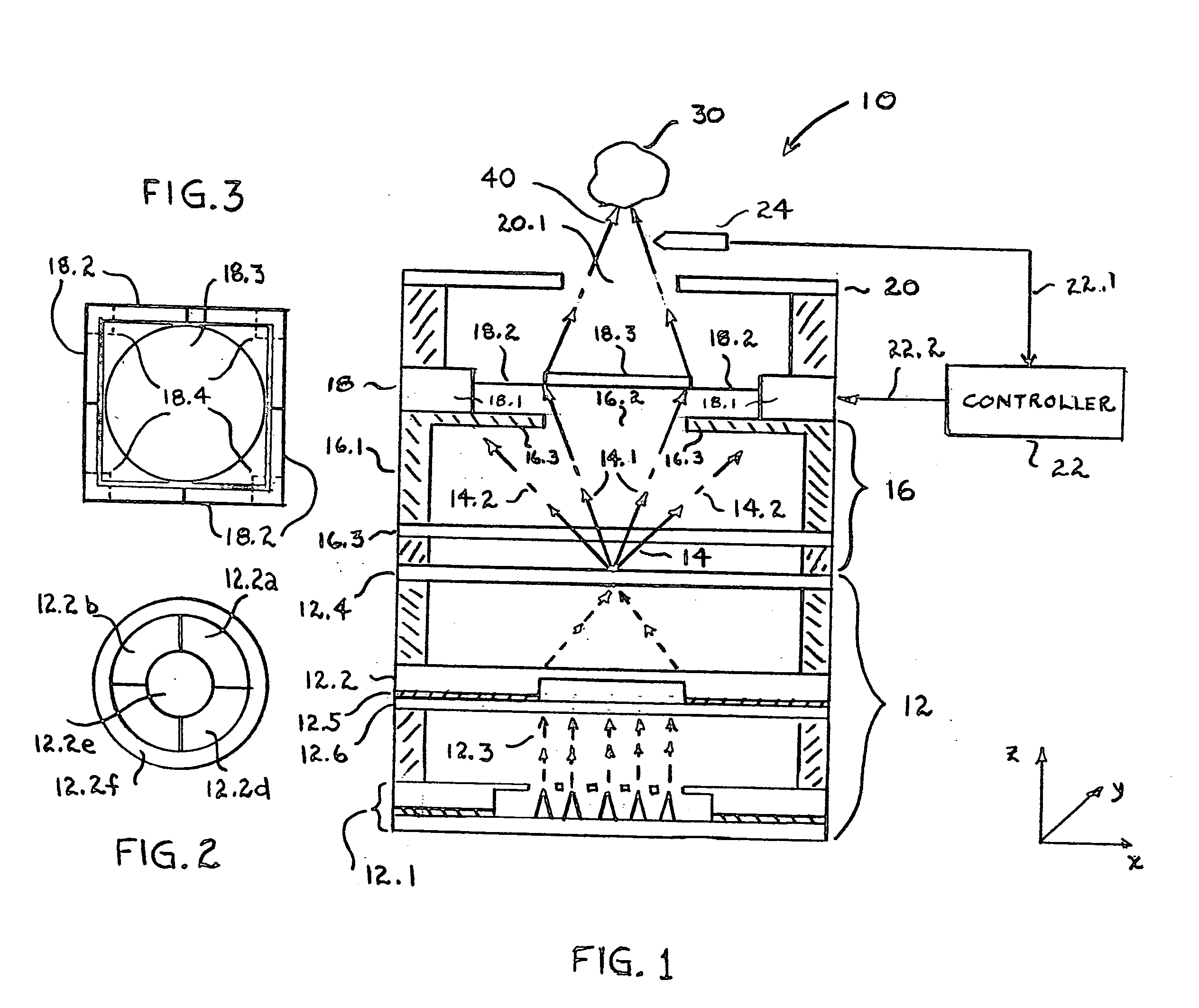
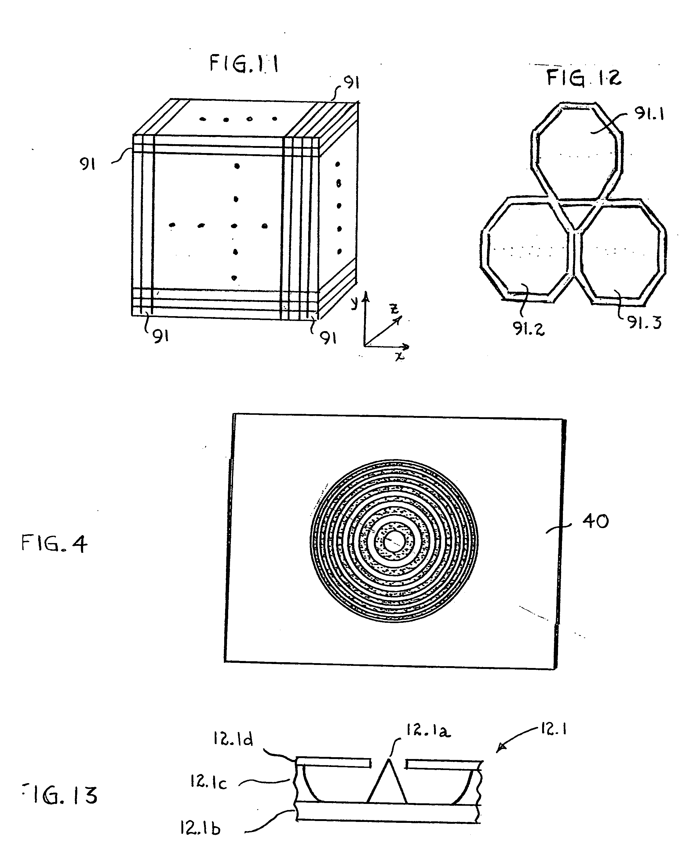
[0027] With reference now to FIG. 1, we show a schematic cross-sectional view of an x-ray apparatus 10 in accordance with one embodiment of our invention. The apparatus 10 is designed to generate an x-ray beam 40 that irradiates a particular diseased tissue region 30 (e.g., a cancerous tumor or plaque on the interior walls of coronary arteries). Illustratively, the x-ray beam 40 is focused to a spot size of less than 100 nm, whereas the dimension of tissue region 30 may be less than 2 mm.

[0028] Apparatus 10 is typically contained within a vacuum chamber (not shown), which is illustratively maintained at a vacuum of about 10−4-10−6 torr by means well known in the art. Moreover, the complete assembly, including the apparatus 10 and the vacuum chamber, is typically mounted on a catheter in order to insert the source into a body vessel or other cavity and thereby convey the apparatus to a point that is proximate diseased tissue region 30.

[0029] Illustratively, the a...


PUM


Abstract

A micro-miniature x-ray apparatus comprises: a first chip subassembly including a source of x-rays including both Bremsstrahlung photons and characteristic x-rays; a second chip subassembly including a filter for transmitting the characteristic x-rays and blocking the Bremsstrahlung photons; a third chip subassembly including a movable element for focusing or collimating the transmitted characteristic x-rays into a beam and means for controlling the position of the focusing element. In one embodiment, the controlling means include a micro-electromechanical system (MEMS). In another embodiment, the position of the movable element determines how the x-ray beam is steered to the focal area. In still another embodiment, the x-ray source includes a field emitter electron source and a target responsive to the electrons for generating x-rays. In this case, the x-ray beam is also steered by selectively energizing the anode segments. In yet another embodiment, the movable element includes a Fresnel zone plate; in still another embodiment it includes an array of poly-capillaries. Advantageously, our x-ray source, including its focusing, collimating and steering components, can be fabricated small enough to be mounted at the end of a catheter. In addition, in some embodiments it can also fabricated sufficiently inexpensively to be disposable after each use.

Description

BACKGROUND OF THE INVENTION [0001] 1. Field of the Invention [0002] This invention relates micro-miniature x-ray apparatus in general and, more particularly, to such apparatuses in which the direction of an x-ray beam can be focused and steered. [0003] 2. Discussion of the Related Art [0004] Several workers in the medical equipment field have proposed miniature x-ray sources for the treatment of maladies such as cancer tumors and coronary artery disease. In general, the source is inserted into body vessels or other body cavities in order to reach and irradiate the diseased area. In one approach, a catheter with a miniature x-ray source is contemplated for irradiation of cardiovascular tissue. For the treatment of a stenosed artery such a catheter has been proposed for use in conjunction with Percutaneous Transluminal Coronary Angeoplasty (PCTA). See, for example, C. Ribbing et al., U.S. Pat. No. 6,477,233 issued on Nov. 5, 2002 and R. Shefer et al., U.S. Pat. No. 6,148,061 issued on...

Claims


Application Information

Patent Timeline
IPC IPC(8): G21K1/00G21K7/00H01J35/00
CPCG21K7/00H01J2235/18H01J2235/068H01J35/00
Inventor PAU, STANLEYTENNANT, DONALD MILAN
Owner LUCENT TECH INC
Why Eureka
Try Eureka