Optical fiber pump multiplexer

a technology of optical fiber and multiplexer, which is applied in the field of optical fiber bundles, can solve the problems of complex manufacturing techniques, difficult to achieve, and the reliability of these prior art pump couplers is not yet fully proven, and achieves the effect of scalability and manufacturing advantages

Inactive Publication Date: 2005-05-19
IMRA AMERICA
View PDF17 Cites 83 Cited by
  • Summary
  • Abstract
  • Description
  • Claims
  • Application Information

AI Technical Summary

Benefits of technology

[0012] In another aspect of the invention, the optical fiber assembly further comprises a glass capillary that maintains the fiber bundle in a predetermined arrangement. The capillary has an inner diameter that is at least as large as the outer diameter of the fiber bundle, and the inner diameter can be at least as large as the outer diameter of the single optical fiber. This allows the capillary to encase a portion of the fiber bundle, and well as the single optical fiber. Preferably, the capillary has a lower refractive index than the cladding of the fibers in the fiber bundle. Alternatively, a polymer coating can cover the splice between the single optical fiber and the fiber bundle, this polymer coating having a lower refractive index than the cladding of the fibers of the fiber bundle.

Problems solved by technology

A major issue in high power fiber amplifiers and lasers is how to couple significant optical power from pump diodes into double clad rare earth doped optical fibers, while maintaining access to the input and output of the fiber amplifiers and lasers.
These two approaches are based on very high power pump diodes for very high power fiber lasers, the reliability of which is not yet fully proven.
Although theoretically it is possible to scale up these two schemes, in practice, it is very difficult to accomplish.
However, production of these prior art pump couplers involves complex manufacturing techniques, entailing pulling a few tens of fibers at the same time by highly precise motion controls in a very controlled manner, while the fibers are heated.
This gets more difficult as this process scales up to more and more fibers.

Method used


Image

  • Optical fiber pump multiplexer
  • Optical fiber pump multiplexer
  • Optical fiber pump multiplexer

Examples


Embodiment Construction

[0029] Prior to describing the presently preferred embodiment of the invention, some details concerning the prior art will be provided to facilitate the reader's understanding of the invention and to set forth the meaning of various terms.

[0030] A detailed description of the preferred embodiments of the invention will now be given referring to the accompanying drawings.

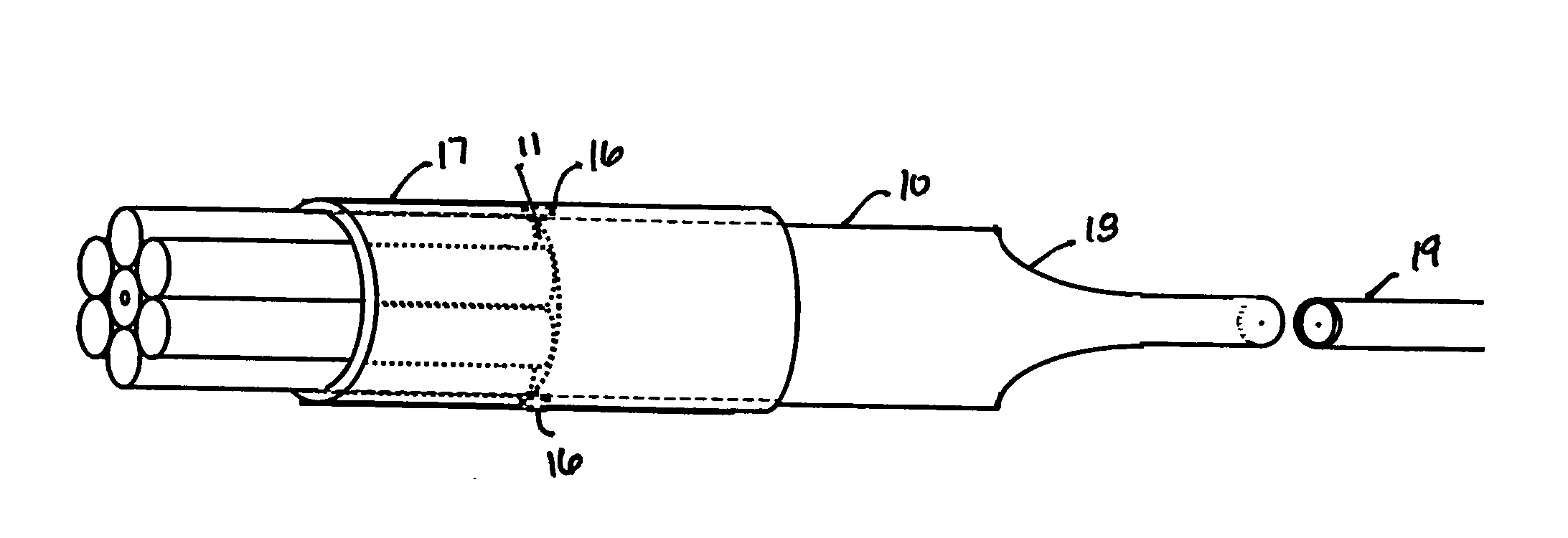
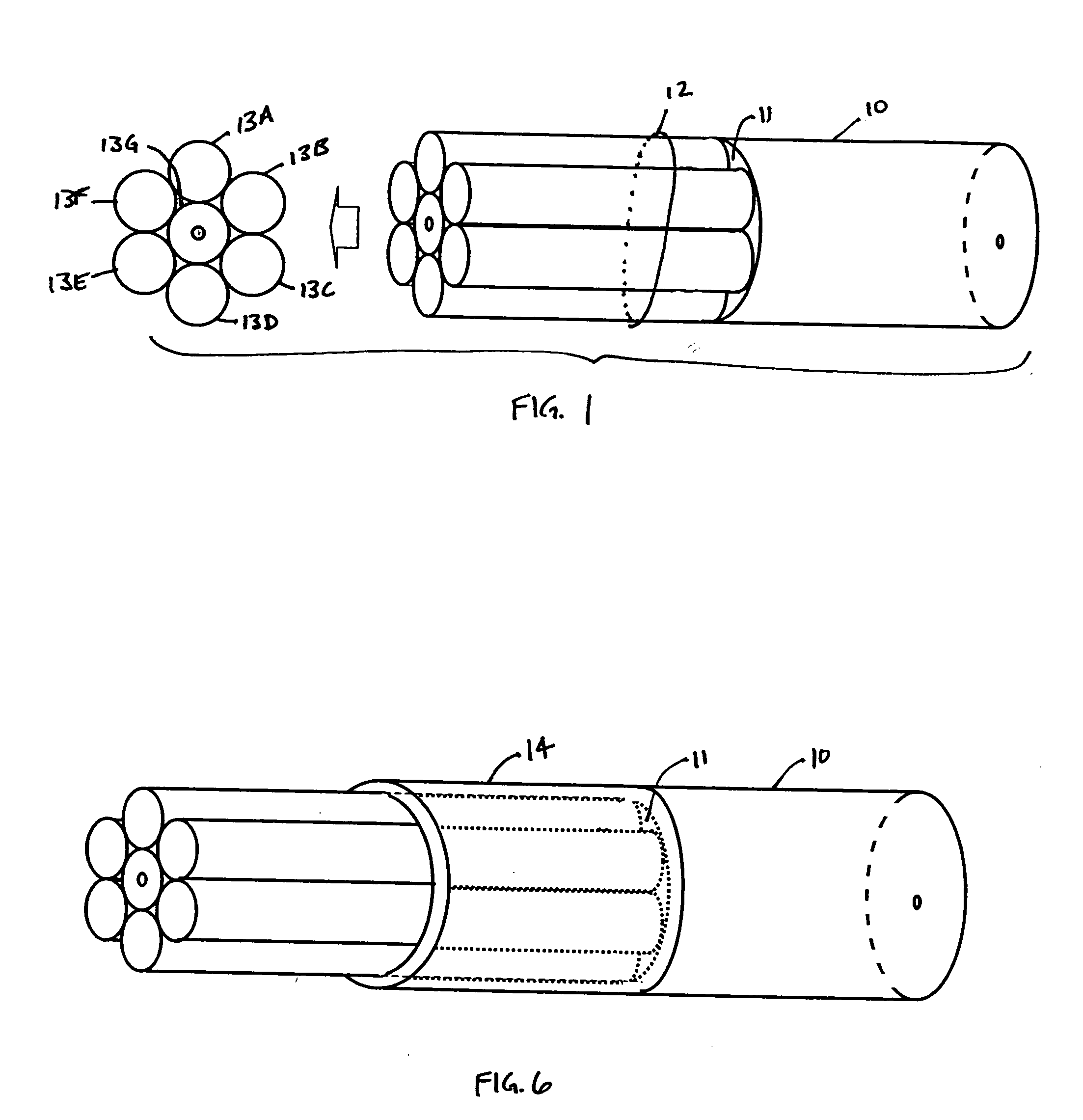
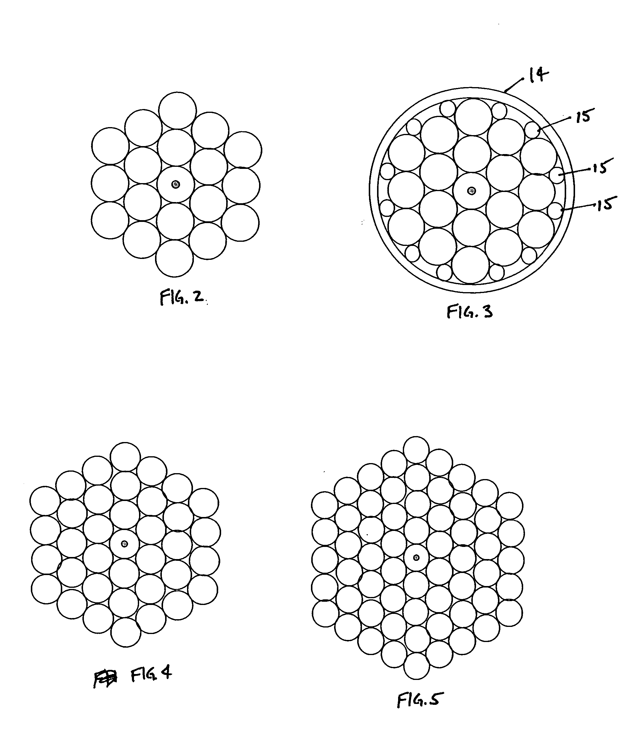
[0031] Referring to FIG. 1, an embodiment of the present invention is illustrated. The basic embodiment is a multimode pump fiber bundle 12 comprising multimode pump fiber pigtails. One or more single mode or few-moded (FM) fibers can be incorporated into the bundle to carry input to a fiber amplifier or output from a fiber amplifier or a fiber laser. The input to the fiber amplifier is at the signal wavelength, which is the wavelength where amplification or lasing takes place. The core fiber 13G can support only single mode operation or a small number of modes. Each of the fibers 13A-13G in the fiber bundle 12 is c...


PUM


Abstract

One or more single mode few-moded or multimode fibers are incorporated into a bundle to carry input to a fiber amplifier or output from a fiber amplifier or a fiber laser. The input is at the signal wavelength, which is the wavelength where amplification or lasing occurs. Each of the fibers in the bundle is cleaved individually or as a group and fiber ends are aligned in the same plane. The fiber amplifier or fiber laser may include a double clad fiber and the other fibers of the bundle couple light for cladding pumping. The device may also include a mode filter for controlling the output mode.

Description

BACKGROUND OF THE INVENTION [0001] 1. Technical Field of the Invention [0002] The present invention is directed to an optical fiber bundle, and more specifically, to an assembly comprising an optical fiber bundle spliced to a single optical fiber, and method of manufacturing the assembly. [0003] 2. Description of the Related Art [0004] A major issue in high power fiber amplifiers and lasers is how to couple significant optical power from pump diodes into double clad rare earth doped optical fibers, while maintaining access to the input and output of the fiber amplifiers and lasers. US20030202547A1, entitled “Multi-mode fiber amplifier”, and hereby incorporated by reference herein, represents an example of this class of devices. This patent describes single mode propagation in multimode fiber, and references such techniques as mode-filtering, the use of few moded fiber, gain-guiding, and other techniques which may find general applicability in connection with the invention. [0005] U....

Claims


Application Information

Patent Timeline
Patent Type & Authority Applications(United States)
IPC IPC(8): G02B6/255G02B6/28
CPCG02B6/2551G02B6/2856H01S3/09408H01S3/094007H01S3/094053H01S3/06754
Inventor DONG, LIANGJ. HARTER, DONALD
Owner IMRA AMERICA
Why Eureka
Try Eureka