Hydrogen supply device and fuel-cell system

Inactive Publication Date: 2005-05-19
DAIHATSU MOTOR CO LTD +1
View PDF1 Cites 9 Cited by
  • Summary
  • Abstract
  • Description
  • Claims
  • Application Information

AI Technical Summary

Benefits of technology

[0016] The hydrogen supply device of the present invention uses the fuel whose standard oxidation-reduction potential is equal to or less than zero, to promote a spontaneous electrolytic reaction of the fuel. This enables elimination of the need for an external power source for triggering the electrolytic reaction, simplification

Problems solved by technology

However, this methanol fuel cell of JP Laid-open (Unexamined) Patent Publication No. 2002-252017 requires an external power source for triggering the electrolytic reaction of methanol first in the electrolyzing unit at the starting of operation of the fuel cell, and a power supply member for supplying the electric power genera

Method used


Image

  • Hydrogen supply device and fuel-cell system
  • Hydrogen supply device and fuel-cell system
  • Hydrogen supply device and fuel-cell system

Examples


Example

Example 1

1) Production of Membrane-electrode Conjunction Member:

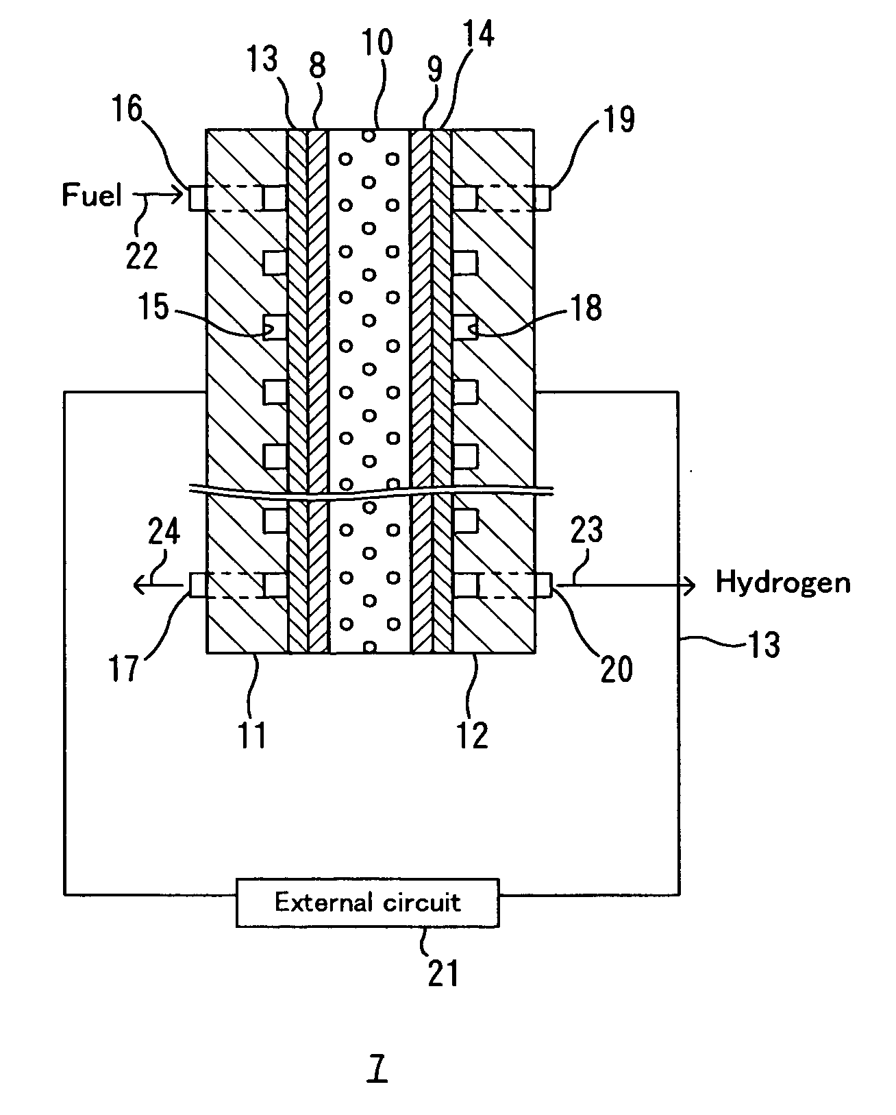
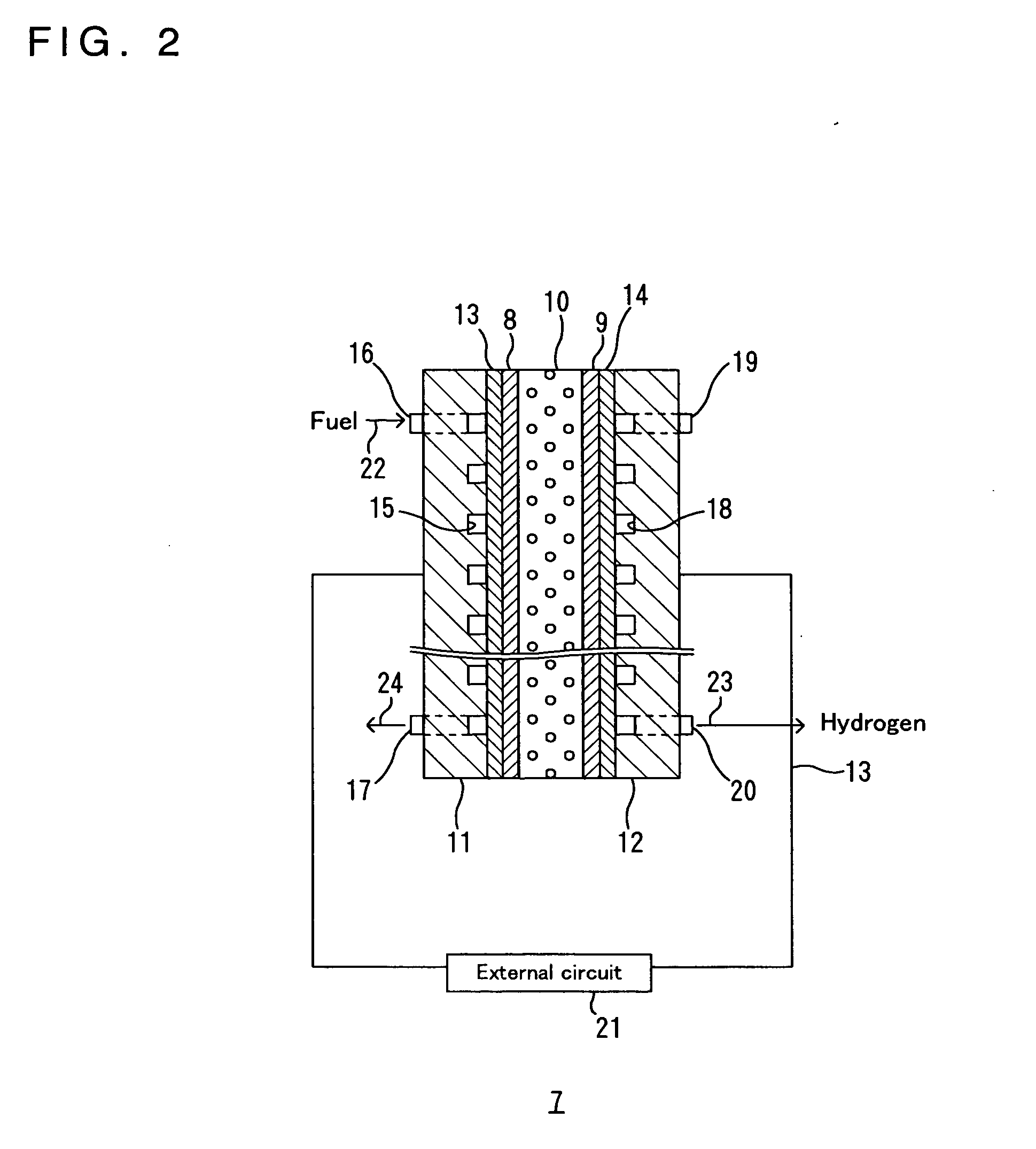
[0081] With H2PtCl6 solution and NaBH4 (reducing agent) placed at both sides of the electrolyte membrane 10 of a cation-exchange, perfluoro-based, polymer electrolyte membrane (Nafion 117® available from Du Pont), the fuel-side electrode 8 of Pt and the hydrogen-production-side electrode 9 of Pt were formed on the both sides of the electrolyte membrane 10, respectively, by electroless plating. An amount of Pt supported on each side of the electrolyte membrane was 1 mg / cm2. The membrane-electrode conjunction member obtained had a circular form and the electrode area was 10 cm2.

2) Production of Hydrogen Supply Device:

[0082] A sintered compact of titanium fiber was used for the collector 13 and a carbon cloth coated with a water-shedding carbon layer was used for the collector 14 with gas diffusion layer. The membrane-electrode conjunction member including the fuel-side electrode 8 and hydrogen-production-side electr...

Example

Example 2

1) Production of Membrane-electrode Conjunction Member:

[0086] With Pt(NH4)6Cl4 solution and NaBH4 (reducing agent) placed at both sides of the electrolyte membrane 10 of an anion-exchange, perfluoro-based, polymer electrolyte membrane (Tosflex SF-17® available from Tosoh Corporation), the fuel-side electrode 8 of Pt and the hydrogen-production-side electrode 9 of Pt were formed on the both sides of the electrolyte membrane 10, respectively, by electroless plating. An amount of Pt supported on each side of the electrolyte membrane 10 was 1 mg / cm2. The membrane-electrode conjunction member obtained had a circular form and the electrode area was 10 cm2.

2) Production of Hydrogen Supply Device:

[0087] A sintered compact of titanium fiber was used for the collector 13 and a carbon cloth was used for the collector 14 with gas diffusion layer. The membrane-electrode conjunction member including the fuel-side electrode 8 and hydrogen-production-side electrode 9 formed on both s...


PUM

PropertyMeasurementUnit
Efficiencyaaaaaaaaaa
Energyaaaaaaaaaa
Reduction potentialaaaaaaaaaa

Abstract

A fuel cell system that can realize generation of electrical energy with improved energy efficiency as well as with a simplified construction of the system, and a hydrogen supply device used in the fuel cell system. The fuel cell system 1 comprises a fuel cell unit 4 using hydrogen as a fuel, and a hydrogen supply device 3 to supply hydrogen gas to the fuel cell unit 4. The hydrogen supply device 3 comprises a fuel-side electrode 8 to decompose a fuel whose standard oxidation-reduction potential is equal to or less than zero, a hydrogen-production-side electrode 9 for producing hydrogen, and an electrolyte membrane 10 interposed between them. This hydrogen supply device 3 can promote a spontaneous electrolytic reaction of the fuel whose standard oxidation-reduction potential is equal to or less than zero. This enables elimination of the need of an external power source for triggering the electrolytic reaction, simplification in construction of the system, and further, generation of the hydrogen with improved energy efficiency. Thus, this fuel cell system 1 can realize the generation of electrical energy with improved energy efficiency as well as with a simplified construction of the system.

Description

BACKGROUND OF THE INVENTION [0001] This application is based on application No.2003-209192 filed in Japan, the content of which is incorporated hereinto by reference. [0002] 1. Field of the Invention [0003] The present invention relates to a hydrogen supply device and to a fuel-cell system. More particularly, the present invention relates to a hydrogen supply device for supplying hydrogen to a fuel cell unit using hydrogen as a fuel and to a fuel-cell system comprising the hydrogen supply device and the fuel cell unit to which hydrogen is supplied from the hydrogen supply device. [0004] 2. Description of the Prior Art [0005] A variety of polymer electrolyte membrane fuel cells (proton-exchange membrane fuel cells) using hydrogen gas as a fuel have been proposed to date. In general, the polymer electrolyte membrane fuel cell has the structure wherein a hydrogen-side electrode and an oxygen-side electrode are placed opposite to each other to sandwich a polymer electrolyte membrane the...

Claims


Application Information

Patent Timeline
IPC IPC(8): C25B1/02C25B9/00C25B13/04H01M8/06H01M8/10H01M8/22
CPCH01M8/0606Y02E60/521H01M8/222H01M8/1002H01M8/1007Y02E60/50
Inventor YAMADA, KOJITANAKA, HIROHISAYASUDA, KAZUAKISIROWA, ZYUNMIYAZAKI, YOSHINORI
Owner DAIHATSU MOTOR CO LTD
Why Eureka
Try Eureka