Method and apparatus for performing high-voltage contactless conductivity (HV-CCD) electrophoresis

a contactless conductivity and electrophoresis technology, applied in the field of high-voltage contactless conductivity (hv-ccd) electrophoresis, can solve the problems of limited amperometric detection, standard uv absorption techniques are generally not applied to capillary electrophoresis on chips, and limited technology, so as to reduce the adherence of the immunoglobulin complex and the effect of reducing the adherence of each immunoglobulin

Inactive Publication Date: 2005-05-26
HAUSER PETER C
View PDF0 Cites 48 Cited by
  • Summary
  • Abstract
  • Description
  • Claims
  • Application Information

AI Technical Summary

Benefits of technology

[0032] In accordance with a thirty-fourth embodiment of the present invention, the thirty-third embodiment is modified so the first sample is injected into the separation channel using a first dc voltage applied for a predetermined period of time. In accordance with a thirty-fifth embodiment of the present invention, the thirty-fourth embodiment is modified so the second sample is injected into the separation channel using a second dc voltage applied for a predetermined period of time. In accordance with a thirty-sixth embodiment of the present invention, the thirty-third embodiment is modified to further include pre-conditioning the separation channel with a basic solution followed by rinsing of the separation channel with a run buffer before injecting either the first sample or the second sample into the separation channel. In accordance with a thirty-seventh embodiment of the present invention, the thirty-third embodiment is modified to further include the step of applying a separation potential between a pair of separation electrodes, wherein one of the separation electrodes is disposed at each end of the separation channel so the immunoglobulin complex migrates along the separation channel. In accordance with a thirty-eighth embodiment of the present invention, the thirty-seventh embodiment is modified so the separation potential applied is a dc voltage. In accordance with a thirty-ninth embodiment of the present invention, the thirty-seventh embodiment is modified to further include the step of applying a detection potential across the detection electrodes, wherein the detection potential is an ac voltage having a predetermined peak-to-peak amplitude and a predetermined frequency. In accordance with a fortieth embodiment of the present invention, the thirty-ninth embodiment is modified so the detection potential has a peak-to-peak amplitude of 4

Problems solved by technology

Microfluidic devices utilizing laser-induced fluorescence (LIF) dominated this field a few years ago, but this technology was limited to systems that could detect species derivatized (i.e., labeled) to render them fluorescent.
On the other hand, standard UV absorption techniques are generally not applied to capillary electrophoresis on chips because the available optical path lengths are too short to make UV techniques practical in this environment.
Amperometric detection is limited to only electroactive species and not much interest has been present in potentiometric techniques.
Wang reported that the most favorable signal-to-noise characteristics of detector circuit 20 occurred at a voltage of 5 Vp-p, although he experimented with the amplitude range of 0-15 Vp-p only to discover that amplitude variation from 5 Vp-p resulted in a nearly linear increase in the noise level and in a reduced baseline stability.
The first drawback to the prior art micromachined capacitively coupled contactless conductivity detection (C4D) system is that the electrodes 13 are glued to the surface of the chip device 1.
As a result, each time a new chip is to be used, the electrodes 13 on the chip must be glued to the chip and attached (i.e., soldered) to the copper wires of the detector circuit 20, which is time intensi

Method used


Image

  • Method and apparatus for performing high-voltage contactless conductivity (HV-CCD) electrophoresis
  • Method and apparatus for performing high-voltage contactless conductivity (HV-CCD) electrophoresis
  • Method and apparatus for performing high-voltage contactless conductivity (HV-CCD) electrophoresis

Examples


first example

The Affect of Grooves on the CE Microchip

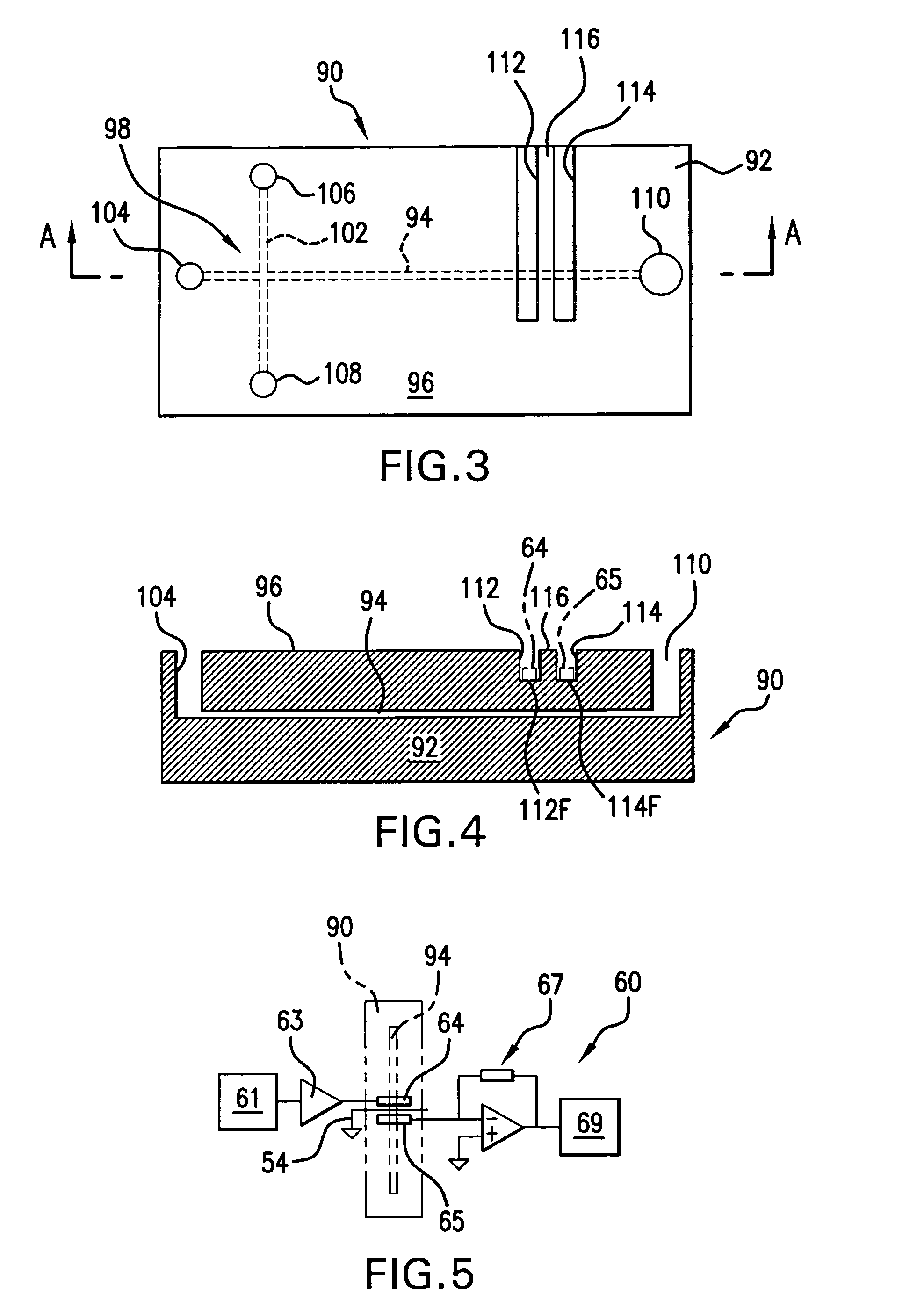
[0077] The first example highlights the affect of having the detection electrodes mounted in grooves on the surface of the microchip 90. The microchips used in this first example are commercially available glass microchips (model MC-BF4-TT100, Micralyne, Edmonton, Canada) containing a standard injection cross. The separation channel is 85 μm long with a semicircular cross section of 50 μm width and 20 μm depth buried approximately 1 mm below the upper surface of the microchip. Grooves for placement of the detection electrodes were made in the upper surface of the microchips either by ultrasonic abrasion, with an imprinting tool, or manually using a cutting wheel attached to a high frequency spindle. In either case, the floor of each groove was situated approximately 0.2 mm from the separation channel, and the detection electrodes were formed on the floor of each groove using conductive silver paint. Each detection electrode was approximately...

second example

The Effect of Applied Frequency to Detector Response

[0081] The second example highlights the effect of applied voltage and frequency on the peak height of analyte detection voltage amplitude. Glass CE microchips having detection electrodes placed in grooves were used for this experiment. In this run, 200 μM of lithium analyte in 10 mM MES / his buffer with 2 mM 18-Crown-6 at pH 6 was analyzed using an injection potential of +0.5 kV for 3 seconds and a separation potential of +3 kV. Actuation voltage potentials of 250 Vp-p, 300 Vp-p, and 500 Vp-p were studied at 50, 100, 200 and 300 kHz.

[0082] As shown in FIG. 9, the optimal lithium analyte detection voltage (i.e., highest detection sensitivity) was observed for the combination of 500 Vp-p actuation potential at a frequency of 50 kHz. It is noted that a more stable baseline was observed for the combination of 500 Vp-p at a frequency of 100 kHz. Thus, optimum analyte detection is a function of both the peak-to-peak voltage amplitude a...

third example

Effect of the Separation Voltage on Detection Peaks

[0083] The third example highlights the effect of varying the separation voltage on the analyte detection voltage peaks. Glass CE microchips having detection electrodes placed in grooves were used for this experiment. In this run, potassium, sodium and magnesium at 20 μM in 10 mM MES / his buffer were analyzed using an injection potential of +0.5 kV for 3 seconds and an actuation voltage of 500 Vp-p at 100 kHz. Separation voltages were increased incrementally from (a)+2 kV, (b)+3 kV, and then to (c)+4 kV.

[0084] At +2 kV, the potassium peak had a migration time of 28 seconds, and all peaks were severely broadened. Increasing the separation voltage lead to shorter migration times, sharper peaks, and better detection limits. Using the +4 kV separation potential and repeating the experiment produced detection limits of 0.49, 0.41, and 0.35 μM for potassium, sodium and magnesium respectively. These observed detection limits for potassium...


PUM

PropertyMeasurementUnit
Lengthaaaaaaaaaa
Electric potential / voltageaaaaaaaaaa

Abstract

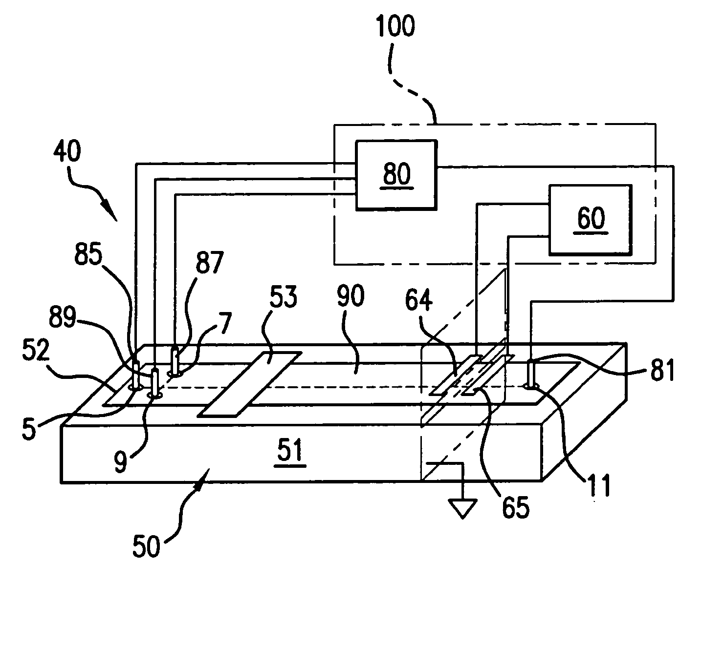
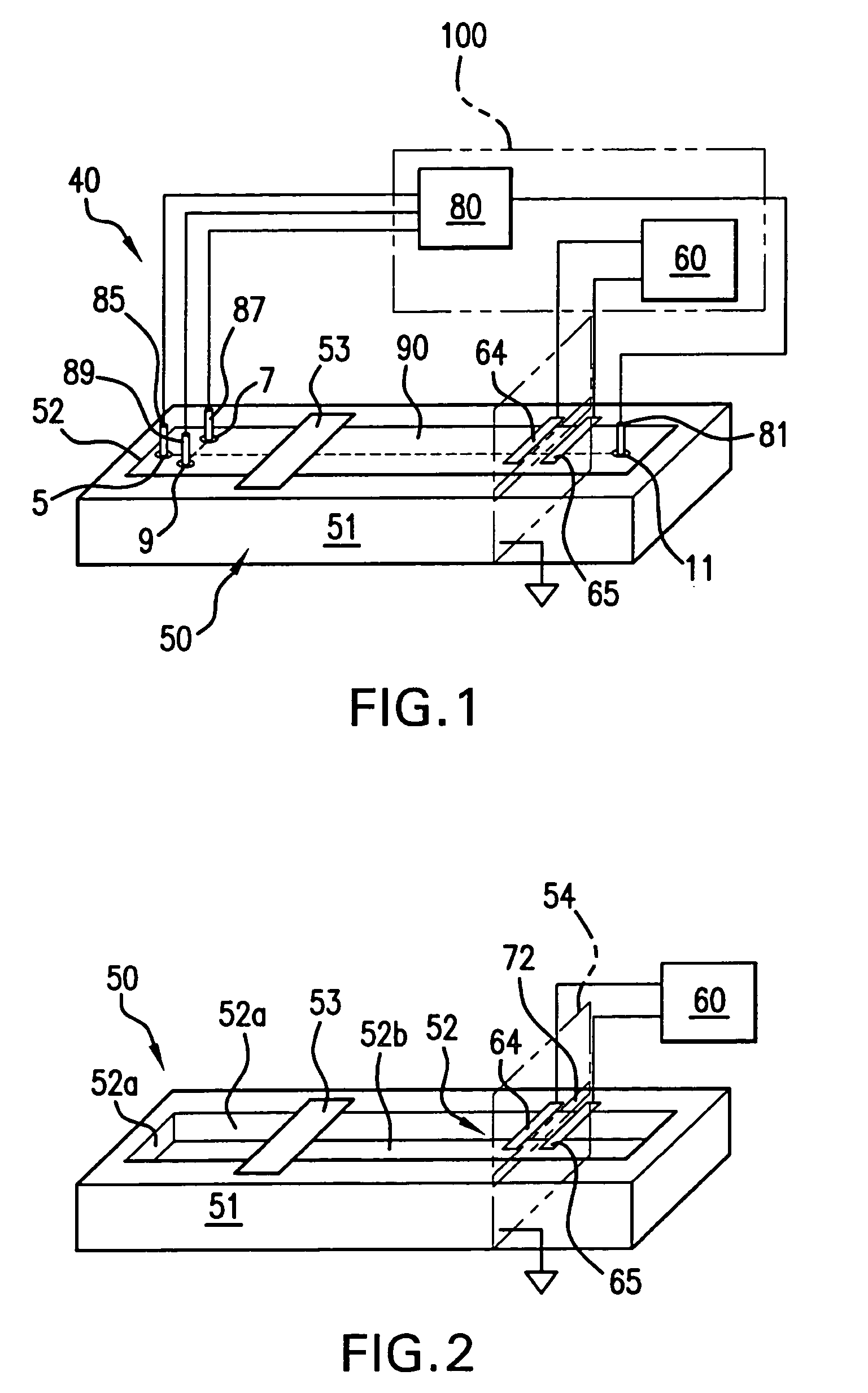
A chip-based capillary electrophoresis assembly including: a holder including a frame for removably receiving a chip; a capillary electrophoresis microchip dimensioned to fit onto the holder, and comprising a body and a separation channel defined in the body; and a pair of adhesive detection electrodes integrated with an electronic conductometric detection circuit, wherein the assembly is assemblable by disposing the capillary electrophoresis microchip on the holder and removably placing the adhesive electrodes on the microchip body near the separation channel. A label-free analyte conductometric detection method and a label-free capillary electrophoresis immunoassay method are also described.

Description

FIELD OF THE INVENTION [0001] The present invention relates to a method and apparatus for performing high-voltage contactless conductivity (HV-CCD) electrophoresis. The invention also relates to several specific applications of the method and apparatus including, for example, label-free immunoassays. BACKGROUND OF THE INVENTION [0002] Microfabricated analytical systems, also known as “lab-on-chip” devices, have recently and dramatically changed the way biochemical and chemical assays are performed. In particular, there has been much interest in micromachined capillary electrophoresis (CE) chips because of their fast and efficient capability to separate certain analyte species. Microfluidic devices utilizing laser-induced fluorescence (LIF) dominated this field a few years ago, but this technology was limited to systems that could detect species derivatized (i.e., labeled) to render them fluorescent. Alternative electrochemical systems and methods directed to amperometry, potentiomet...

Claims


Application Information

Patent Timeline
IPC IPC(8): G01N27/447
CPCG01N27/44791G01N27/4473
Inventor HAUSER, PETER C.ABAD VILLAR, EVA MARIATANYANYIWA, JATISAI
Owner HAUSER PETER C
Why Eureka
Try Eureka