Dielectric ceramic compositions and electronic devices

a technology of dielectric ceramics and compositions, applied in the direction of fixed capacitor details, inorganic insulators, fixed capacitors, etc., can solve the problems of not disclosing the composition amount rate, reducing the service life of the insulation resistance, and being unreliable, so as to achieve low ir defect rate , the effect of high relative dielectric constan

Active Publication Date: 2005-05-26
TDK CORPARATION
View PDF3 Cites 13 Cited by
  • Summary
  • Abstract
  • Description
  • Claims
  • Application Information

AI Technical Summary

Benefits of technology

[0024] According to the present invention, even when dielectric layer of multilayer ceramic capacitor is made thinner and laminated in multiple numbers, dielectric ceramic composition having low IR defect rate and high relative dielectric constant can be obt...

Problems solved by technology

For the internal electrode past, normally Pd or Pd alloys have been used, however, instead of the costly Pd, relatively low priced Ni or Ni alloys are being used.
But multilayer ceramic capacitor having the internal electrode made of Ni or Ni alloys, in comparison to the internal electrode made of Pd manufactured by firing in an atmosphere, had problems of being short...

Method used


Image

  • Dielectric ceramic compositions and electronic devices
  • Dielectric ceramic compositions and electronic devices
  • Dielectric ceramic compositions and electronic devices

Examples


example 1

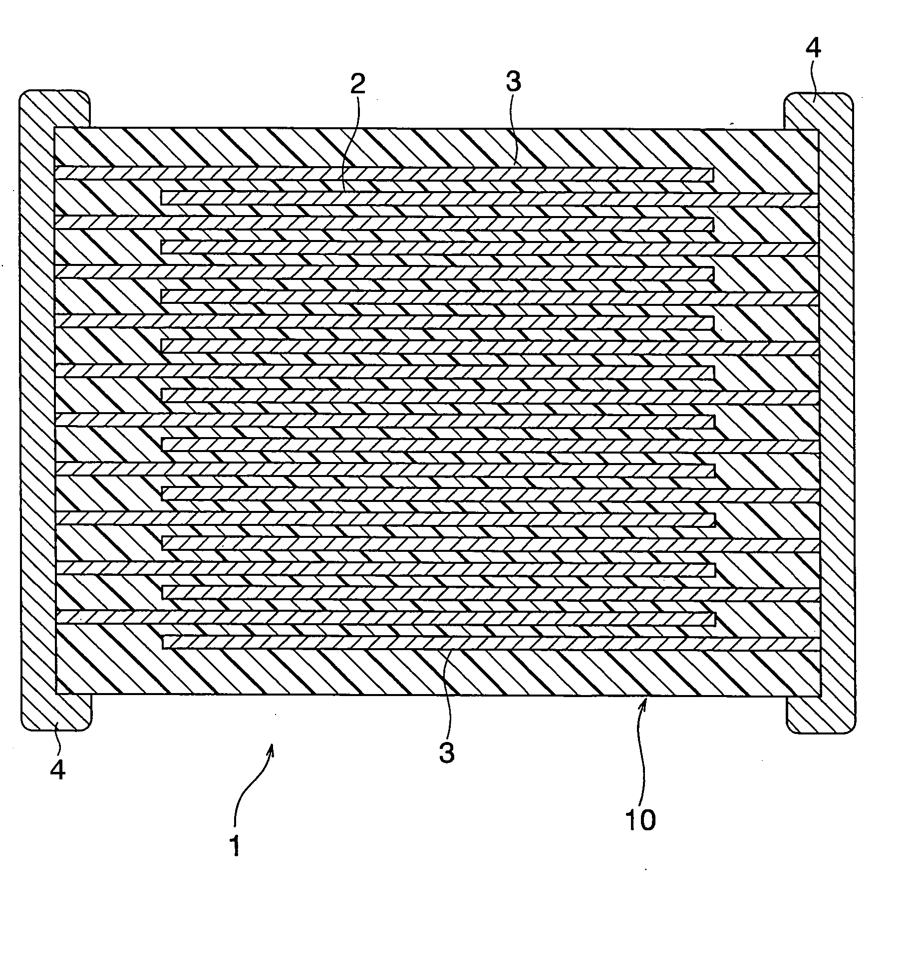
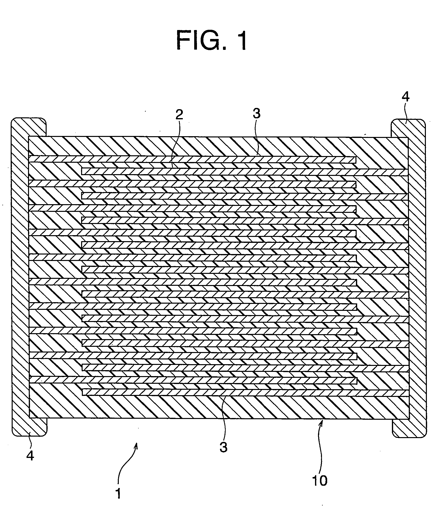
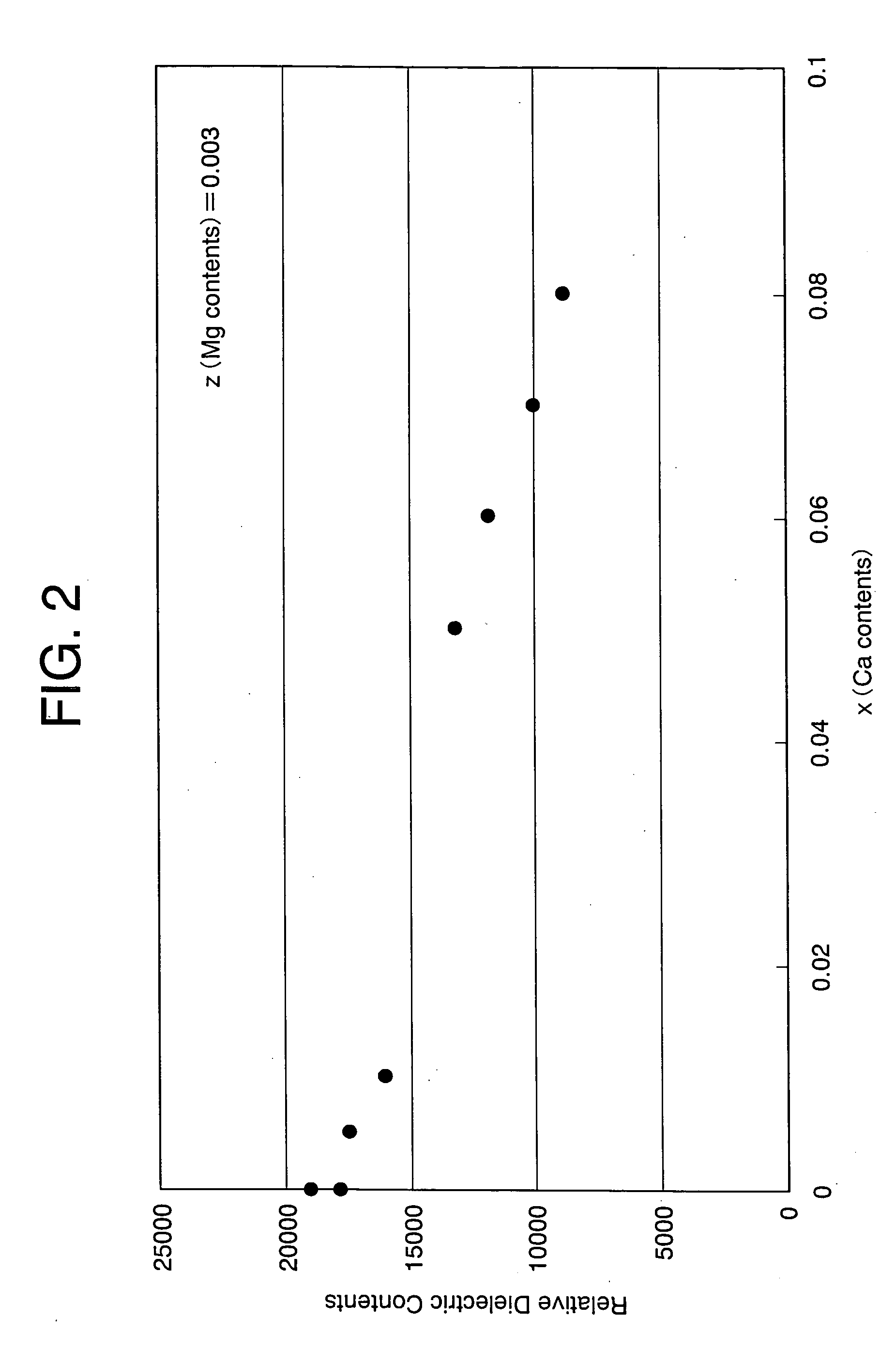
[0085] Dielectric oxide having a main component of {{Ba(1-x)Cax}O}A{Ti(1-y-z)ZryMgz}BO2 was manufactured by sol-gel synthesis making the contents of symbols x and z, showing the composition rates, as stated in tables 1 and 2. And the contents of other symbols A, B and y were made as following; A / B=0.989 to 1.004 and y=0.16. Further, the samples of the present embodiment were A / B=0.995 to 1.004.

[0086] Further, as subcomponent, with respect to 100 mol of the main component, 0.4 mol of MnO, 0.3 mol of Y2O3, 0.04 mol of V2O5, 0.08 mol of WO3 and 0.8 mol of SiO2 were wet-grinded for 20 hours by ball mill. Then, the mixture was fired in atmosphere at 900° C. for 4 hours and the obtained fired material was subjected to wet grinding by ball mill for 20 hours and added as a subcomponent. Then, the main component and the subcomponent were subjected to wet grinding for 19 hours by ball mill and then dried to obtain dielectric materials of samples 1 to 32 shown in tables 1 and 2.

[0087] By the...

example 2

[0115] Capacitor samples of samples 34 to 41 as shown in table 3 were prepared in the same way as the samples in example 1 except WO3 as oxide of W was not added. And in the same way as example 1, relative dielectric constant and IR defect rate can be measured.

TABLE 3xzRelativeIRSample(Ca(MgDielectricDefectFiringNo.content)content)ConstantRateDecisionTemperature34Comp.00.00317950AbnormalX1260Ex.particlegrowth35Comp.0.00010.003191130◯1240Ex.36Ex.0.0050.003176540◯124037Ex.0.010.003162930◯124038Ex.0.050.003133780◯124039Ex.0.060.003120050◯124040Comp.0.070.003101450◯1240Ex.41Comp.0.080.00390030X1240Ex.

[0116] Here, with respect to 100 mol of {{Ba(1-x)Cax}O}A{Ti(1-y-z)ZryMgz}BO2 wherein A / B=0.989 to 1.004 and y=0.16, 0.4 mol of MnO, 0.3 mol of Y2O3, 0.04 mol of V2O5, 0.08 mol of SiO2 are included.

[0117] Evaluation 3

[0118] Table 3 shows composition rate, firing temperature, relative dielectric constant and IR defect rate of capacitor samples 34 to 41 prepared in example 2. Further, each...


PUM

PropertyMeasurementUnit
Thicknessaaaaaaaaaa
Substance countaaaaaaaaaa

Abstract

In order to provide dielectric ceramic composition having low IR defect rate and high relative dielectric constant even when the multilayer ceramic capacitor is made thinner, dielectric ceramic composition including a main component expressed by a composition formula {{Ba(1-x)Cax}O}A{Ti(1-y-z)ZryMgz}BO2 and subcomponents of Mn oxide, Y oxide, V oxide and Si oxide is provided. In the above formula, A, B, x , y and z are as follows: 0.995≦A/B≦1.020, 0.0001≦x≦0.07, preferably 0.001≦x≦0.05, 0.1≦y≦0.3 and 0.0005≦z≦0.0 1, preferably 0.003≦z≦0.0 1.

Description

BACKGROUND OF THE INVENTION [0001] 1. Field of the Invention [0002] The present invention relates to dielectric ceramic compositions used such as dielectric layer of multilayer ceramic capacitor and electronic devices used as dielectric layer of the dielectric ceramic compositions. [0003] 2. Description of the Related Art [0004] Multilayer ceramic capacitor is broadly used as small size, large capacity and highly reliable electronic device and that a large number of the multilayer ceramic capacitors is used in electric equipments and electronic equipments. Recently, as equipments get smaller in size and higher in performance, demands for smaller size, larger capacity, lower cost and higher reliability for the multilayer ceramic capacitor are becoming more strict. [0005] Multilayer ceramic capacitors are normally manufactured by laminating the internal electrode layer paste and dielectric slurry (paste) by sheet method or printing method and firing them. For the internal electrode pa...

Claims


Application Information

Patent Timeline
IPC IPC(8): B32B18/00C04B35/46C04B35/468H01B3/12H01G4/12H01G4/30
CPCC04B35/468H01G4/30H01G4/1227H01G4/12
Inventor ITO, KAZUSHIGEYURI, SHUNICHINAKANO, YUKIEMIYAUCHI, MARIHIBI, TAKAKOIWANAGA, DAISUKEHOSONO, MASAKAZU
Owner TDK CORPARATION
Why Eureka
Try Eureka