Implantable system for monitoring the condition of the heart

Active Publication Date: 2005-05-26
ANGEL MEDICAL SYST
View PDF24 Cites 112 Cited by
  • Summary
  • Abstract
  • Description
  • Claims
  • Application Information

AI Technical Summary

Benefits of technology

[0015] A “tracker system” as defined herein includes implanted electrical leads which are part of an implanted cardiotracker plus external equipment that includes external alarm means and a physician's programmer. The present invention is the tracker system for monitoring the degradation of a patient's cardiovascular condition from one or more causes. These causes include the rejection of a transplanted heart and further include the progression of a stenosis in a coronary artery; e.g., as one or more stenoses in a coronary artery become progressively more narrow thereby causing reduced blood flow to the heart muscle. As less and less blood is available to the heart muscle, the patient's ST segment will shift during exertion by an ever increasing amount. Eventually, if the stenosis severely restricts blood flow or a plaque rupture occurs, a thrombus can form causing an AMI. By noting changes over time in the shift of ST segment voltage in relation

Problems solved by technology

AMI is a common and life-threatening complication of coronary artery disease.
Those with coronary atherosclerosis are at higher risk for AMI if the plaque becomes further obstructed by thrombus.
However, without knowing the patient's normal (i.e., baseline) ECG pattern, detection from a standard 12 lead ECG can be unreliable.
The Reveal also does not have the capability to measure ST segment shift.
In fact, its high pass filtering and electrode spacing preclude accurate detection of changes in the low frequency aspects of the heart's electrical signal, which low frequency aspects are required for the detection of ischemia.
While pacemakers track the numbers of beats paced or not pa

Method used


Image

  • Implantable system for monitoring the condition of the heart
  • Implantable system for monitoring the condition of the heart
  • Implantable system for monitoring the condition of the heart

Examples


Embodiment Construction

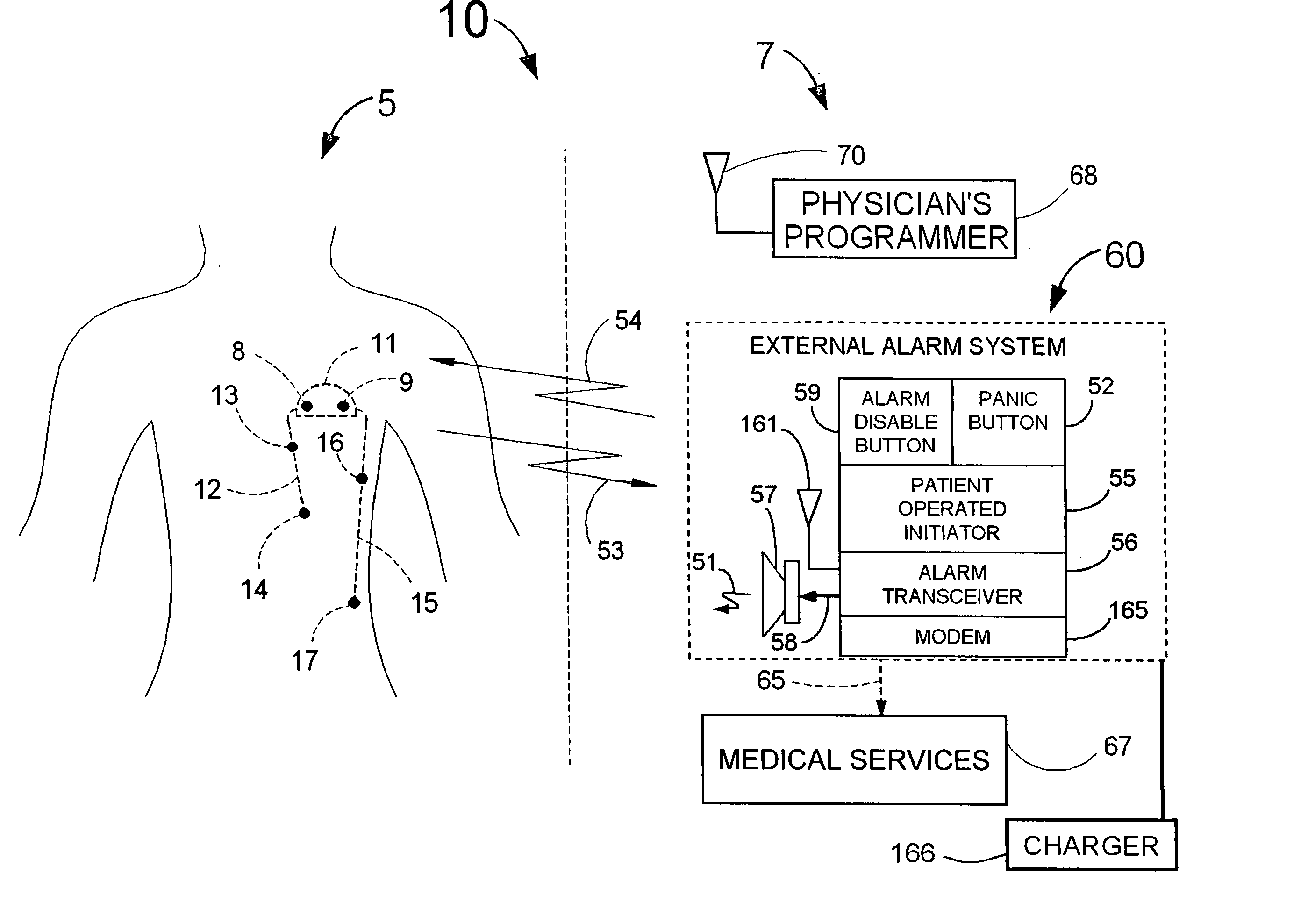
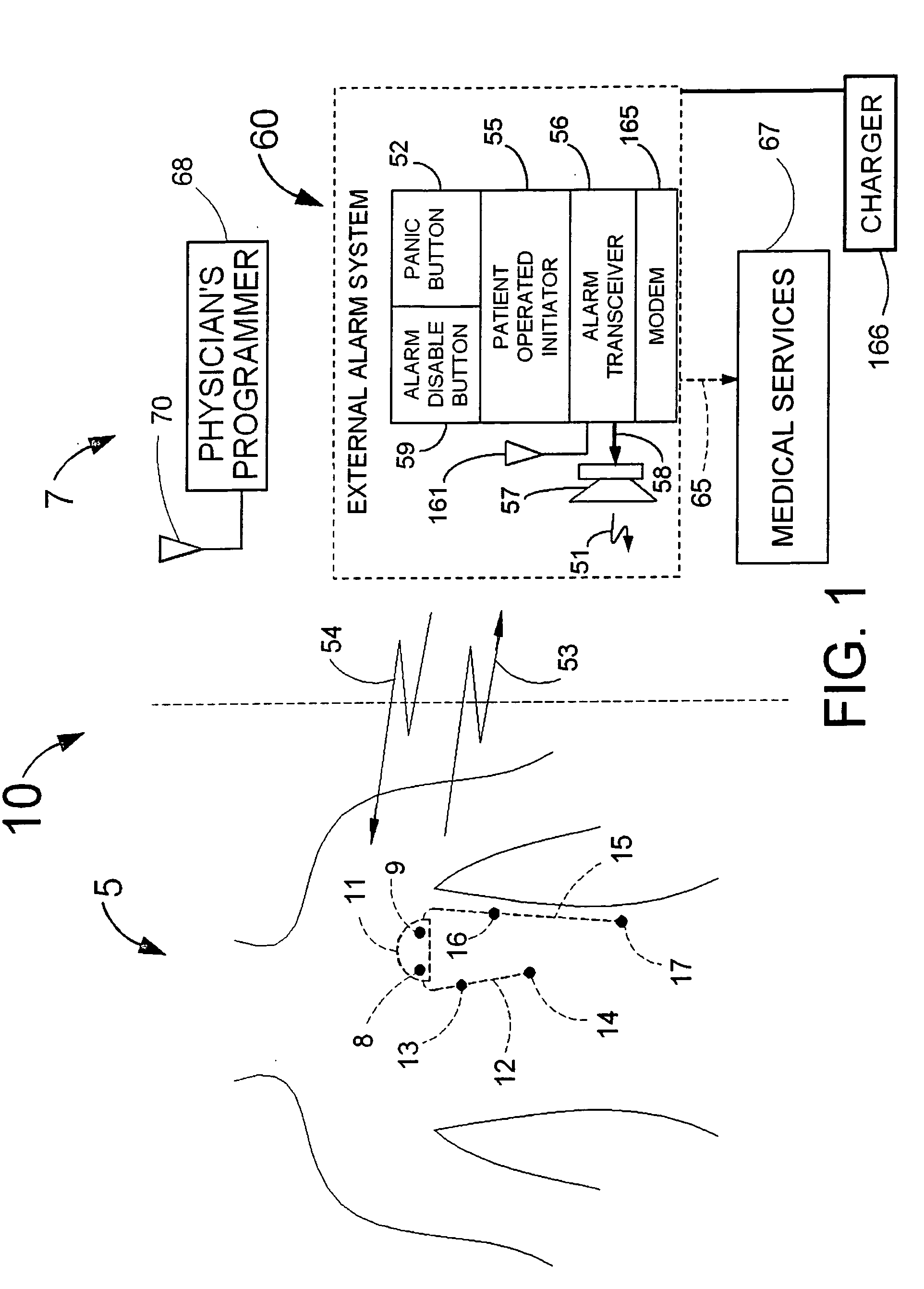
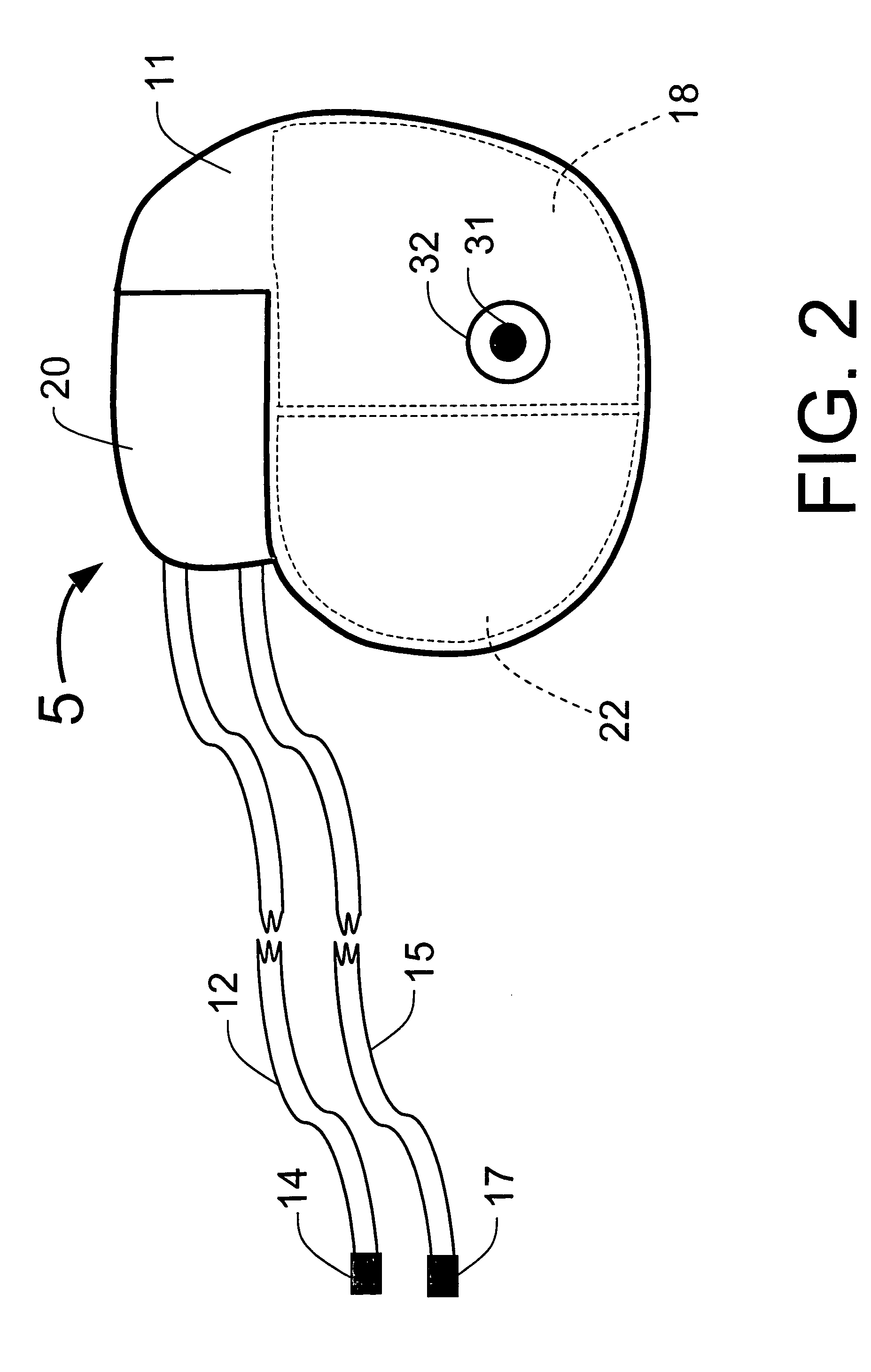
[0110]FIG. 1 illustrates an example of a tracker system 10 including an implanted cardiotracker 5 and external equipment 7. The cardiotracker 5 includes electrical wire leads 12 and 15 and a battery-powered electronics module contained within a metal case 11. The cardiotracker 5 can track the patient's cardiovascular condition over extended periods of time. The cardiotracker 5 can also detect acute cardiac events including acute myocardial infarction and arrhythmias and warn the patient when such an event occurs. The cardiotracker 5 can also track slowly changing cardiac functions such as day-to-day changes in QRS voltage that can be indicative of the rejection of a transplanted heart. The cardiotracker 5 can record the patient's electrogram signal for later review by a medical practitioner. The cardiotracker 5 can capture histogram-based historical representations of one or more heart signal parameters for later analysis and review by a medical practitioner. The cardiotracker 5 can...


PUM


Abstract

Disclosed is a “tracker system” that includes implanted electrical leads which are part of an implanted cardiotracker plus external equipment that includes external alarm means and a physician's programmer. The tracker system is designed to monitor the degradation of a patient's cardiovascular condition from one or more causes. These causes include the rejection of a transplanted heart and/or the progression of a stenosis in a coronary artery. As one or more stenoses in a coronary artery become progressively more narrow thereby causing reduced blood flow to the heart muscle coronary circulation, the tracker system can alert the patient by either or both internal and/or external alarm means to take the appropriate medical action. The physician's programmer can be used to display histograms of key heart signal parameters that are indicative of the patient's cardiovascular condition.

Description

CROSS REFERENCE TO RELATED APPLICATIONS [0001] This is the utility patent application based upon the provisional patent application Ser. No. 60 / 524,873, entitled “System for Monitoring Cardiovascular Condition” filed provisionally on Nov. 26, 2003.FIELD OF USE [0002] This invention is in the field of systems that monitor a patient's cardiovascular condition using implanted devices that interact with other devices located externally to the patient. BACKGROUND OF THE INVENTION [0003] Heart disease is the leading cause of death in the United States. A heart attack (also known as an acute myocardial infarction (AMI)) typically results from a thrombus (i.e., a blood clot) that obstructs blood flow in one or more coronary arteries. AMI is a common and life-threatening complication of coronary artery disease. Myocardial ischemia is caused by an insufficiency of oxygen to the heart muscle. Ischemia is typically provoked by physical activity or other causes of increased heart rate when at le...

Claims


Application Information

Patent Timeline
IPC IPC(8): A61B5/352A61B5/00A61B5/366A61N1/372
CPCA61B5/0031A61B5/0452A61B5/0472A61N1/37247A61N1/025A61N1/37235A61B5/413A61B5/366A61B5/349A61B5/358A61B5/355
Inventor FISCHELL, DAVID R.FISCHELL, ROBERT E.HARWOOD, JONATHANJOHNSON, STEVEN R.
Owner ANGEL MEDICAL SYST
Why Eureka
Try Eureka