
Software controller for handling system

a software controller and handling system technology, applied in the field of semiconductor manufacturing, can solve the problems of large space occupation, linear tools, cluster tools, etc., and achieve the effect of dampening the vibration of the robotic arm facility and reducing the resonant vibration of the end effector

Inactive Publication Date: 2005-05-26
BLUESHIFT TECH +2
View PDF77 Cites 49 Cited by
  • Summary
  • Abstract
  • Description
  • Claims
  • Application Information

AI Technical Summary

Benefits of technology

[0027] A manufacturing facility described herein may include a robotic component; a workpiece; and a sensor for monitoring a process performed on the workpiece by the robotic component. The sensor may include at least one of a light sensor, a contact sensor, a proximity sensor, a sonic sensor, a capacitive sensor, and a magnetic sensor. The sensor may include a vertical proximity sensor. The sensor may include a horizontal proximity sensor. The system may include a plurality of sensors diagonally arranged. The system may include a plurality of proximity sensors in a plurality of locations. The sensor may include a sensor for detecting movement of one or more of the workpiece, the robotic component, or an effector arm. The system may include a plurality of sensors used to determine a position of the robotic component. The system may include a plurality of sensors positioned to detect a final position of the robotic component. The final position may be an extended position or a retracted position or an interim position between an extended position and a retracted position. The sensor may provide a signal used to verify a path of the workpiece. The sensor may detect the workpiece shifting out of location. The fabrication process may be stopped in response to a signal from the sensor that the workpiece has shifted out of location. The robotic arm may move the workpiece to a safe location. The robotic arm may move the workpiece automatically. The robotic arm may move the workpiece under user control. The sensor may be used to prevent collision of at least one of the robotic arm or the workpiece with the manufacturing facility.
[0096] As used herein, the term “SCARA arm” refers to a robotic arm that includes one or more links and may include an end effector, where the arm, under control, can move linearly, such as to engage an object. A SCARA arm may have various numbers of links, such as 3, 4, or more. As used herein, “3-link SCARA arm” shall include a SCARA robotic arm that has three members: link one (L1), link two (L2) and an end effector. A drive for a 3-link SCARA arm usually has 3 motors: one connected to L1, one to the belt system, which in turn connects to the end effector through pulleys and a Z (lift) motor. One can connect a fourth motor to the end effector, which allows for some unusual moves not possible with only three motors.

Problems solved by technology

Cluster tools, machines that arrange a group of semiconductor processing modules radially about a central robotic arm, take up a large amount of space, are relatively slow, and, by virtue of their architecture, are limited to a small number of semiconductor process modules, typically a maximum of about five or six.
Linear tools, while offering much greater flexibility and the potential for greater speed than cluster tools, do not fit well with the current infrastructure of most current semiconductor fabrication facilities; moreover, linear motion of equipment components within the typical vacuum environment of semiconductor manufacturing leads to problems in current linear systems, such as unacceptable levels of particles that are generated by friction among components.
Among other problems with rail-type linear systems is the difficulty of including in-vacuum buffers, which may require sidewall mounting or other configurations that use more space.
Also, in a rail-type system it is necessary to have a large number of cars on a rail to maintain throughput, which can be complicated, expensive and high-risk in terms of the reliability of the system and the security of the handled materials.
Furthermore, in order to move the material from the cart into a process module, it may be necessary to mount one or two arms on the cart, which further complicates the system.
With a rail system it is difficult to isolate sections of the vacuum system without breaking the linear motor or rail, which can be technically very complicated and expensive.
The arm mounted to the cart on a rail system can have significant deflection issues if the cart is floated magnetically, since the arm creates a cantilever that is difficult to compensate for.
The cart can have particle problems if it is mounted / riding with wheels on a physical rail.
The sensor may be used in a hazardous environment.
The load lock will have a large thermal mass, and so it may only react slowly to changes in the desired temperature.

Method used


Image

  • Software controller for handling system
  • Software controller for handling system
  • Software controller for handling system

Examples


Embodiment Construction

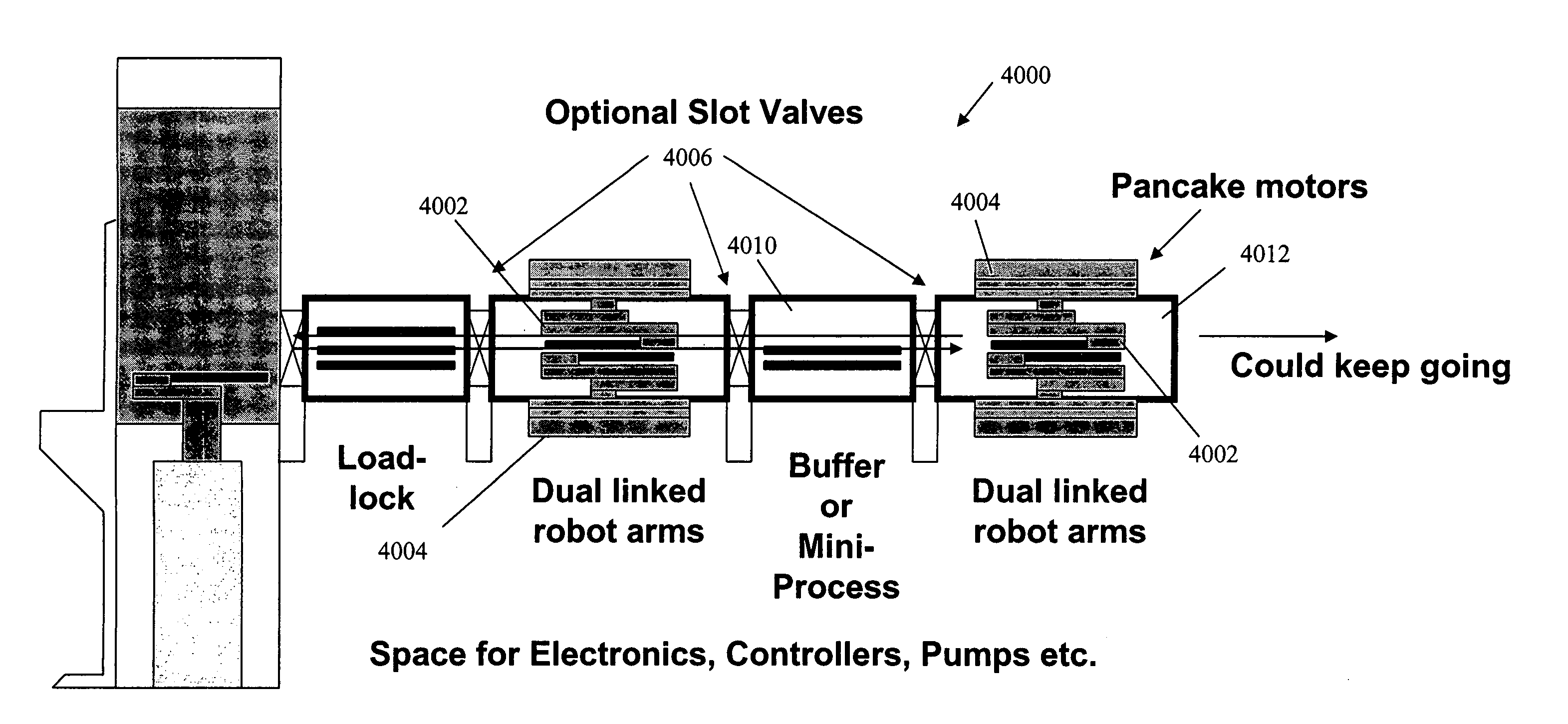
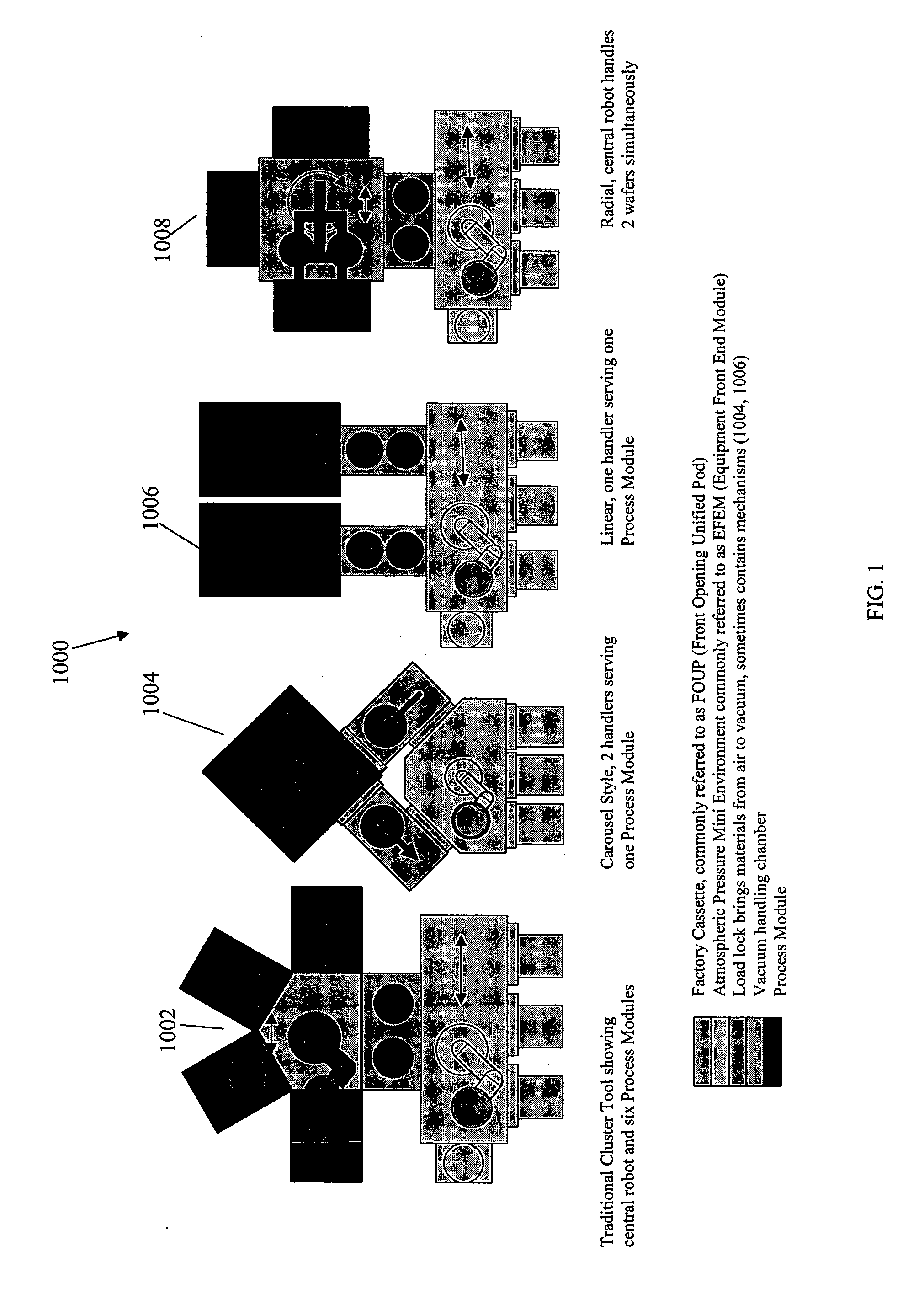
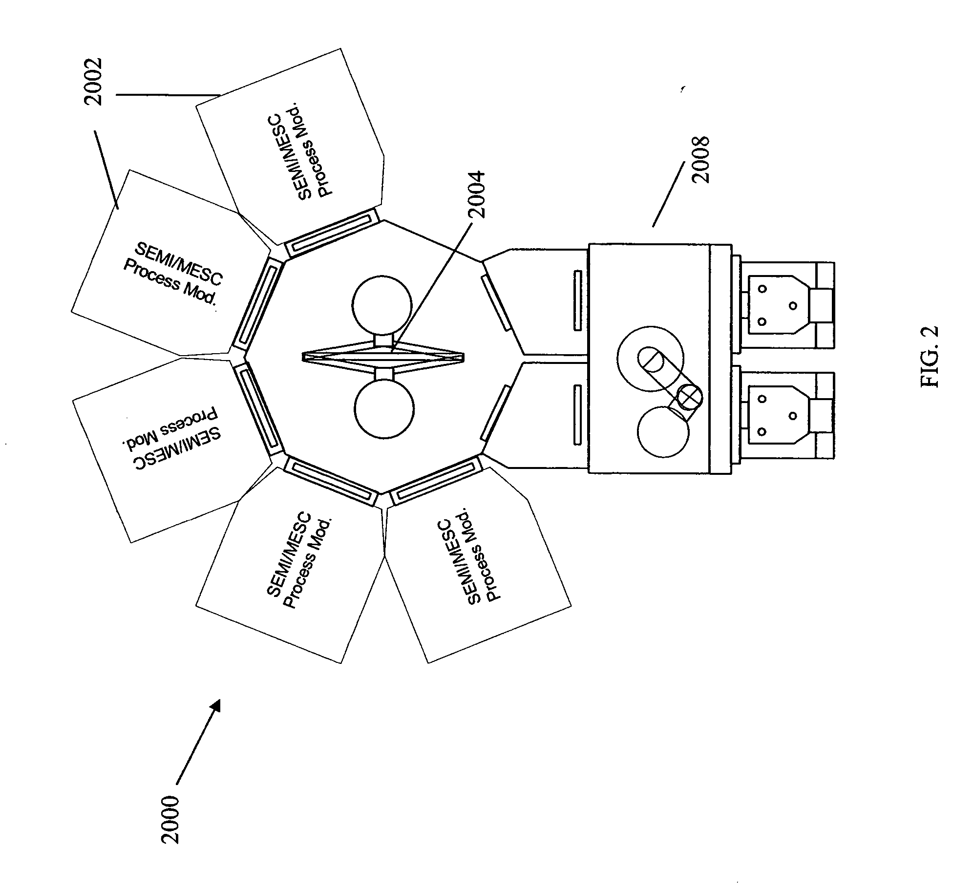
[0167]FIG. 1 shows equipment architectures 1000 for a variety of manufacturing equipment types. Each type of manufacturing equipment handles items, such as semiconductor wafers, between various processes, such as chemical vapor deposition processes, etching processes, and the like. As semiconductor manufacturing processes are typically extremely sensitive to contaminants, such as particulates and volatile organic compounds, the processes typically take place in a vacuum environment, in one or more process modules that are devoted to specific processes. Semiconductor wafers are moved by a handling system among the various processes to produce the end product, such as a chip. Various configurations 1000 exist for handling systems. A prevalent system is a cluster tool 1002, where process modules are positioned radially around a central handling system, such as a robotic arm. In other embodiments, a handling system can rotate items horizontally, such as in the embodiment 1004. An import...


PUM


Abstract

Methods and systems are provided for controlling material handling systems, such as vacuum-based semiconductor handling systems. In embodiments a central software controller recognizes the addition of a component to the system, such as the addition of a process module or robotic handling facility, and can optimize material flow based on the new component. In embodiments the system may include software for visualizing and optimizing the flow of materials and / or the configuration of the system.

Description

CROSS-REFERENCE TO RELATED APPLICATIONS [0001] This application claims the benefit under 35 U.S.C. § 119(e) of the following U.S. Provisional Applications: [0002] Ser. No. 60 / 518,823, filed Nov. 10, 2003, entitled “Methods and Systems for Semiconductor Manufacturing;” and [0003] Ser. No. 60 / 607,649, filed Sep. 7, 2004, entitled “Methods and Systems for Semiconductor Manufacturing.”[0004] Each of the foregoing applications are incorporated herein by reference.BACKGROUND [0005] 1. Field of the Invention [0006] This invention relates to the field of semiconductor manufacturing, and more particularly to machines used for material transport in a vacuum handling system. [0007] 2. Description of the Related Art [0008] Current semiconductor manufacturing equipment takes several different forms, each of which has significant drawbacks. Cluster tools, machines that arrange a group of semiconductor processing modules radially about a central robotic arm, take up a large amount of space, are re...

Claims


Application Information

Patent Timeline
IPC IPC(8): B25J17/00B65G1/00B66C1/00F26B5/04F26B13/30G06F7/00G06F19/00H01LH01L21/00H01L21/677
CPCB25J9/042Y10T74/20305H01L21/67161H01L21/67167H01L21/67173H01L21/67178H01L21/67184H01L21/6719H01L21/67196H01L21/67201H01L21/67207H01L21/67253H01L21/67259H01L21/67727H01L21/67733H01L21/67736H01L21/67742H01L21/67745H01L21/67748H01L21/67754H01L21/67757H01L21/67781H01L21/68H01L21/68707H01L21/68735Y10S414/139Y10S414/137Y10S414/135H01L21/67126H01L21/67706
Inventor VAN DER MEULEN, PETER
Owner BLUESHIFT TECH
Features
  • Generate Ideas
  • Intellectual Property
  • Life Sciences
  • Materials
  • Tech Scout
  • Unparalleled Data Quality
  • Higher Quality Content
  • 60% Fewer Hallucinations
Learn More