Distributed vehicle service method and system

a technology for vehicles and services, applied in the direction of instruments, transportation and packaging, structural/machine measurement, etc., can solve the problems of inability to conveniently or easily update each individual system, the product had little or no flexibility to interchange and update different hardware and software elements, and the new version of the system often takes years to complete, so as to achieve the effect of reducing the size of software stored locally

Inactive Publication Date: 2005-05-26
TT IP
View PDF17 Cites 89 Cited by
  • Summary
  • Abstract
  • Description
  • Claims
  • Application Information

AI Technical Summary

Benefits of technology

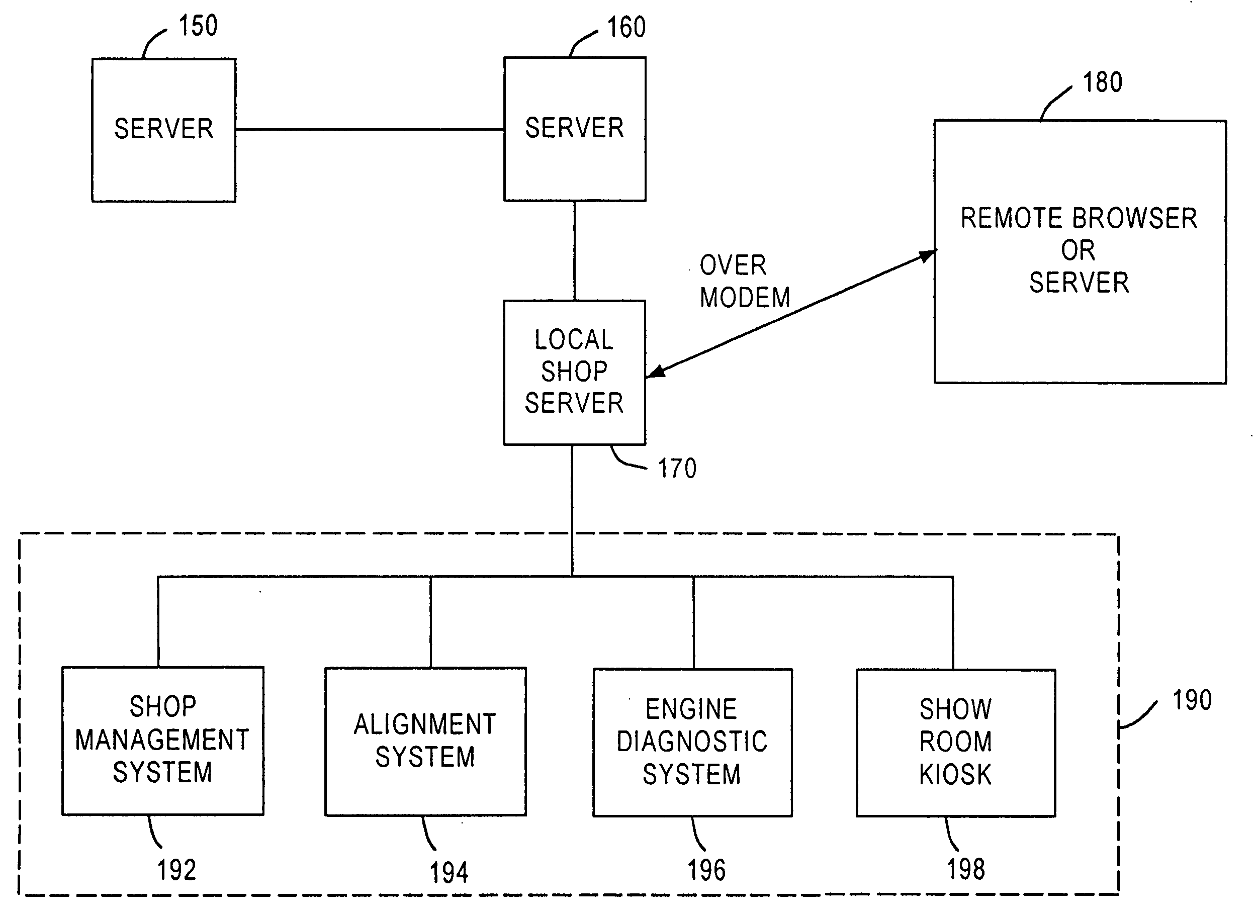
[0030] Since the information necessary for conducting the vehicle diagnostic analysis is distributed in different systems connecting to each other with a data communication network, a local automotive service system can minimize the size of software stored locally and can access most of the information and / or algorithm required to conduct the vehicle diagnostic analysis from a remote system. In addition, updates of the information can take place seamlessly without affecting the local system. The remote system that allows information access by other systems can calculate usage charge based on a per-use basis.

Problems solved by technology

The modern automotive service bay contains numerous expensive pieces of equipment designed to automate servicing of an automobile.
The manufacturer had to customize the software to run on a single dedicated computer, and the resulting product had little or no flexibility to interchange and update different hardware and software elements.
Each individual system also was incapable of being conveniently or easily updated.
Not only did new versions often take years to complete.
It was also so costly to release a new system that, as a practical matter, the manufacturer would have to wait until enough improvements occurred in order to justify the financial burdens of a new version release.
This hampered the ability of the end user, the automotive service professional, to bring the latest technological improvements to the customer, the typical car driver.
Furthermore, such prior art automotive service equipment systems were not generally designed to communicate or cooperate with other computers in the service bay and elsewhere.
This redundancy wasted valuable operator time and promoted key-entry errors.
This, however, limits the information to being stored as files and does not support real-time data flow or a distributed application.
These data-only files, then, did not give the resulting automotive service equipment system the capability of exporting data to a remote location for processing, and then returning the processed data to the original location.
They also did not give the resulting system the capability to locate different portions of a single automotive service equipment application on different computers.
The prior art automotive service equipment system computers also did not communicate with any remote off-site computer to submit in real-time the data gathered by the sensors in the course of effecting a service procedure.
Hence, it was not possible for sensors to transmit their data in real-time to a remote site for analysis and inspection at that remote site.
There was no way for an off-site technician and / or an off-site computer to review the data to evaluate whether the alignment angles were within specification.
Likewise, there was no way for an on-site technician to present this real-time angle information to an off-site expert for purposes of either troubleshooting problems with the servicing equipment, or for receiving instructions and advice on how to proceed with an alignment procedure.
Moreover, for automotive service equipment that depended on OEM and manufacturer generated specifications, such as vehicle wheel alignment equipment, the danger of obsolescence presented itself every new model year.
Otherwise, the service bay might have to turn customers away, or worse, the attendants might service newer vehicles to erroneous specifications.
The administrative task of maintaining updated specifications for the computerized equipment was an additional burden on the personnel running the service centers.

Method used


Image

  • Distributed vehicle service method and system
  • Distributed vehicle service method and system
  • Distributed vehicle service method and system

Examples


Embodiment Construction

[0034]FIG. 4 shows a block diagram of an exemplary automotive service equipment system according to the disclosure. The system of FIG. 4 is used to conduct a diagnostic analysis of vehicle components, such as the engine, brakes, suspension or alignment. While FIG. 4 shows an exemplary automotive service system in its general form, the description herein will, by way of example, occasionally describe the operation of an exemplary vehicle wheel aligner, such as that disclosed in U.S. Pat. No. 4,383,370 or 5,208,646, implementing various features according to this disclosure.

[0035] Data input controller 200 is a computer, which may contain a microprocessor and a memory coupled thereto (not shown). Controller 200 comprises a general purpose portable computer (PC), such as an Intel Pentium-based IBM compatible computer, although any hardware platform suitably programmed will work just as well. Data input controller 200 receives data input from a measurement device 210. In a wheel alignm...


PUM


Abstract

A method and system for conducting a vehicle service comprises the steps of receiving signals representative of vehicle parameters, accessing data and/or software necessary for performing the vehicle service from at least one remote computer over a data transmission network, and performing signal processing related to the vehicle service based on the signals representative of the vehicle parameters and the accessed data and/or software. Since the data and/or software necessary for conducting the vehicle diagnostic analysis is distributed in different systems that are connected via a data communication network, an automotive service system can minimize the size of software stored locally and can access most of the information and/or algorithm required for conducting the vehicle diagnostic analysis from a remote system.

Description

RELATED APPLICATIONS [0001] This application is a continuation-in-part of copending application Ser. No. 10 / 066,795, titled “NETWORK-BASED METHOD AND SYSTEM FOR DISTRIBUTING DATA,” assigned to the assignee herein, which is a continuation-in-part of U.S. patent application Ser. No. 10 / 054,793, filed Jan. 25, 2002, now issued as U.S. Pat. No. 6,560,516 and assigned to the assignee herein, which is a continuation of patent application Ser. No. 08 / 962,023, filed Oct. 31, 1997, now issued as U.S. Pat. No. 6,405,111 and assigned to the assignee herein, which is a continuation-in-part of patent application Ser. No. 08 / 857,725, now issued as U.S. Pat. No. 6,285,932 and assigned to the assignee herein. All of the above-identified applications are incorporated herein by reference.FIELD OF THE DISCLOSURE [0002] The present disclosure relates to a distributed method and system for providing vehicle services, and more specifically, to a method and system for accessing data or software for conduc...

Claims


Application Information

Patent Timeline
Patent Type & Authority Applications(United States)
IPC IPC(8): B60R16/02B60R16/03H04L29/06H04L29/08
CPCB60R16/0315G07C5/008H04L12/2803H04L29/06H04L67/2823H04L69/329H04L67/2819H04L67/12H04L67/2842H04L67/28H04L67/2838H04L67/34H04L67/564H04L67/567H04L67/565H04L67/56H04L67/568H04L9/40
Inventor ROGERS, STEVEN W.GILL, GEORGE M.BELLEFEUILLE, JEAN DEKLING, MIKEBAIRD, MICHAEL L.
Owner TT IP
Why Eureka
Try Eureka