
Method of producing silicon carbide sintered body jig, and silicon carbide sintered body jig obtained by the production method

a technology of silicon carbide and body jigs, which is applied in the field of producing methods of silicon carbide sintered body jigs obtained by the production method, can solve the problems of shortening the processing time of molding, and achieve the effects of shortening the processing time, improving density and corrosion resistance of the surface of the sic boat, and simplifying the processing facilities

Inactive Publication Date: 2005-06-02
BRIDGESTONE CORP
View PDF4 Cites 2 Cited by
  • Summary
  • Abstract
  • Description
  • Claims
  • Application Information

AI Technical Summary

Benefits of technology

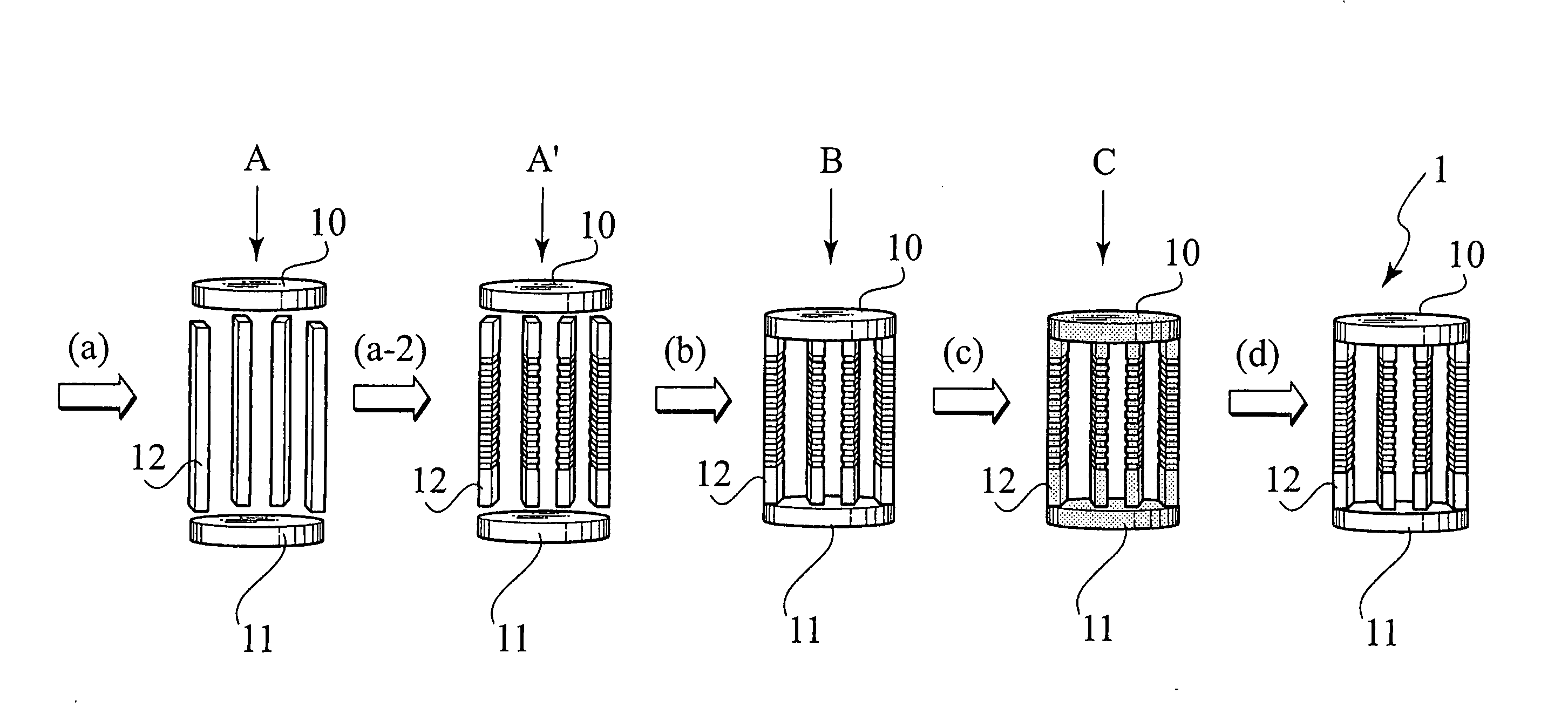
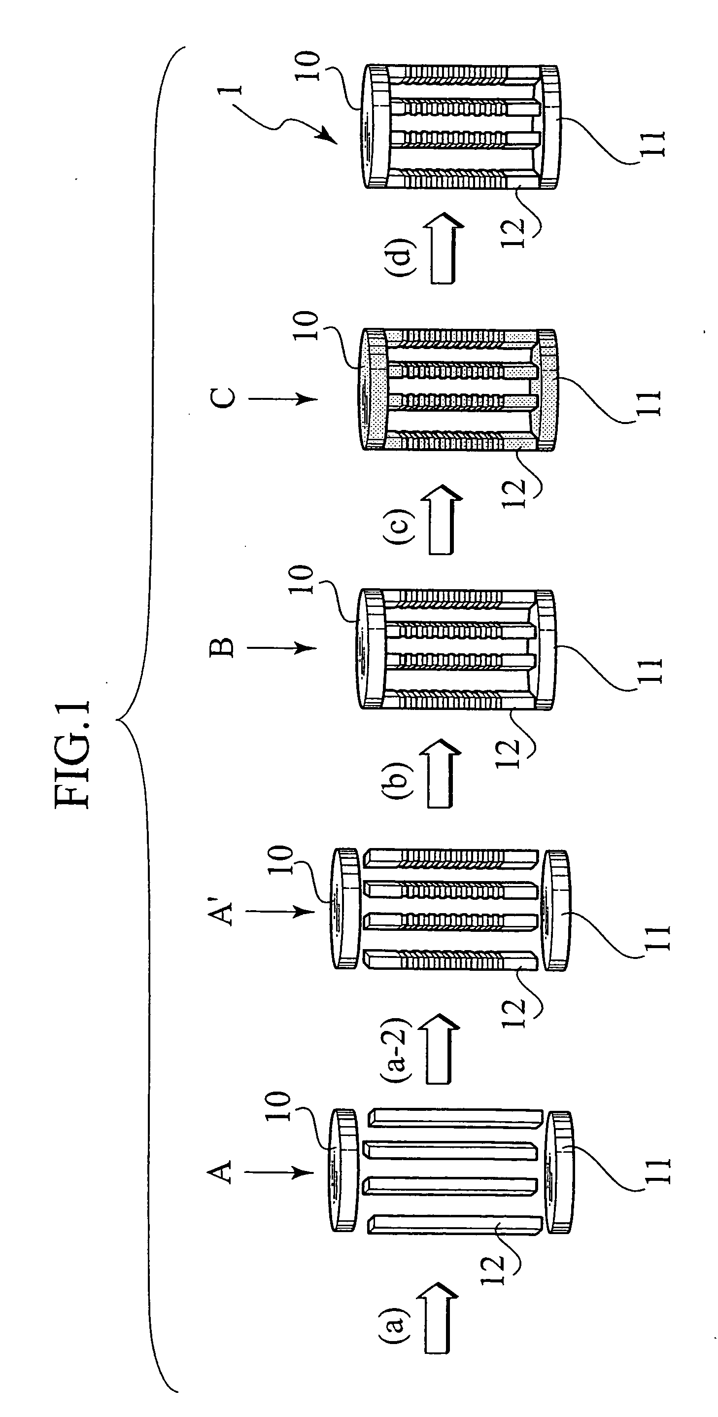
[0021] According to the first aspect of the invention, the molding processing time of a silicon carbide sintered body can be shortened by obtaining a silicon carbide sintered body via molding of a temporarily-sintered body having given strength. Further, a silicon carbide sintered body jig having high purity and high corrosion resistance is obtained.
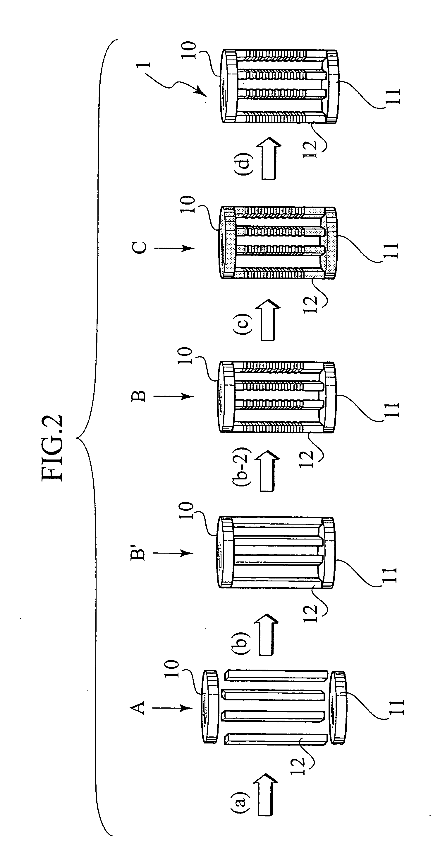
[0037] According to the second aspect of the invention, an action effect is obtained that the density and corrosion resistance of the surface of a SiC boat are improved. There is also obtained an action effect that processing time is shortened and processing facilities are simplified by improvement of the processability of a SiC boat.

Problems solved by technology

However, the above-mentioned silicon carbide sintered body obtained by a reaction sintering method needs efforts and time for molding processing due to high strength, consequently, it is required to shorten molding processing time.
Though the present inventors have suggested a method of conducting temporary molding processing at the stage of production of a green body as a means of solving the above-mentioned problem, a considerate care for producing a molded body has been required due to insufficient strength of a green body.

Method used


Image

  • Method of producing silicon carbide sintered body jig, and silicon carbide sintered body jig obtained by the production method
  • Method of producing silicon carbide sintered body jig, and silicon carbide sintered body jig obtained by the production method
  • Method of producing silicon carbide sintered body jig, and silicon carbide sintered body jig obtained by the production method

Examples


example 1

[0124] First, to 100 parts of a high purity silicon carbide powder having a central particle size of 2.1 μm (silicon carbide having an impurity content of 5 ppm or less produced according to a production method described in JP-A No. 9-48605) was added 40 parts of water, 0.3 parts of deflocculant and 3 parts of a binder, further, they were dispersed and mixed in a ball mill for 24 hours, to obtain a mixed powder in the form of slurry having a viscosity of 15 poise, as a silicon carbide powder.

[0125] This mixed powder in the form of slurry was cast into a gypsum mold having a length of 60 mm, a width of 10 mm and a thickness of 5 mm, and naturally dried at 22° C. for 24 hours, to obtain a green body.

[0126] Next, the resulted green body was heated up to 1800° C. under a vacuum atmosphere, and temporarily-sintered at the above-mentioned temperature for 1 hour to obtain a temporarily-sintered body.

[0127] On the resulted temporarily-sintered body, temporarily-molding processing was per...

example 2

[0130] A temporarily-molded body was obtained in the same manner as in Example 1, then, a phenol resin as a carbon source was impregnated into the temporarily-molded body to obtain a carbon source-impregnated temporarily-molded body which was temporarily-sintered at 1800° C. under a vacuum atmosphere or inert gas atmosphere.

[0131] Then, a Si impregnation treatment was conducted at 1540° C. using metal silicon as a Si source. The resulted reaction sintered body jig was precisely-processed, to obtain a silicon carbide reaction sintered body jig.

example 3

[0143] First, a high purity silicon carbide powder having a central particle size of 1.1 μm (silicon carbide having an impurity content of 5 ppm or less produced according to a production method described in JP-A No. 9-48605) was used as a silicon carbide powder. To this silicon carbide powder was added a phenol resin as a carbon source in given amount according to a conventionally known method, water, deflocculant and binder, respectively, further, they were dispersed and mixed in a ball mill for 24 hours, to obtain a mixed powder in the form of slurry having a viscosity of 50 poise.

[0144] This mixed powder in the form of slurry was cast into a gypsum mold, and naturally dried at 22° C. for 24 hours and dried at 110° C., then, machine processing into given form was conducted, to obtain a green body composed of constituent parts of an upper plate, lower plate and struts. The resulted green body was heated up to 1800° C. under a vacuum atmosphere, and temporarily-sintered at the abo...


PUM

PropertyMeasurementUnit
Temperatureaaaaaaaaaa

Abstract

A method of producing a silicon carbide sintered body jig using a reaction sintering method, comprising: (a)dispersing a silicon carbide powder and an organic substance as a carbon source in a solvent, to produce a mixed slurry powder, (b) pouring the resulted slurry powder into a mold and drying this to obtain a green body, (c) temporarily-sintering the resulted green body under a vacuum atmosphere at 1800° C., to obtain a temporarily-sintered body, (d) temporarily-molding said temporarily-sintered body, to obtain a temporarily-molded body, (e) impregnating a melted metal silicon into the resulted temporarily-molded body by a capillary phenomenon and reacting free carbon in said temporarily-molded body with silicon sucked into said temporarily-molded body by a capillary phenomenon, to obtain a silicon carbide sintered body, and (f) subjecting the resulted silicon carbide sintered body to precise processing, to obtain a silicon carbide sintered body jig.

Description

[0001] This application claims the benefit of priority based on Japanese Patent Applications filed prior to this application, namely, Japanese Patent Application No. 2002-65899 (application date., Mar. 11, 2002) and Japanese Patent Application No. 2002-169656 (application date, Jun. 11, 2002), the specifications of which are incorporated herein by reference. BACKGROUND OF THE INVENTION [0002] 1. Field of the Invention [0003] The present invention relates to a method of producing a silicon carbide sintered body jig used for producing semiconductors and a silicon carbide sintered body jig obtained by the above-mentioned production method. [0004] 2. Description of the Related Art [0005] Conventionally, silicon carbide sintered bodies are paid to attention as materials used in a high temperature region, due to excellent properties such as high temperature strength, heat resistance, abrasion resistance and chemical resistance. Lately, silicon carbide sintered bodies are used as alternati...

Claims


Application Information

Patent Timeline
IPC IPC(8): C04B35/573H01L21/673
CPCC04B35/573C04B35/62625C04B2235/383C04B2235/3834C04B2235/48C04B2235/5436H01L21/67306C04B2235/72C04B2235/77C04B2235/96C04B2235/9607C04B2235/9623C04B2235/9684C04B2235/6581C04B35/56C04B35/565
Inventor MOTOYAMA, TSUYOSHITAGUCHI, JIN-ICHIODAKA, FUMIOSHINOGAYA, TOSHIKAZU
Owner BRIDGESTONE CORP
Learn More