
Electrochromic windows and method of making the same

a technology of electrochromic windows and windows, applied in the field of windows, can solve the problems of difficult mass production, low life expectancy of electrochromic windows, and inability to be widely accepted commercially, and achieve the effects of less expensive components, less cost, and less cos

Inactive Publication Date: 2005-06-02
GENTEX CORP
View PDF29 Cites 32 Cited by
  • Summary
  • Abstract
  • Description
  • Claims
  • Application Information

AI Technical Summary

Benefits of technology

The present invention provides an improved electrochromic window construction that is easier to mass-produce and uses less expensive components. The window has better color stability, improved thermal deflection / emission characteristics, and a sealed chamber between the substrates that prevents leakage. The invention also provides a method for making an electrochromic device with these improved features. Overall, the invention provides a more reliable and efficient solution for creating electrochromic windows and devices.

Problems solved by technology

Electrochromic windows have not been widely accepted commercially for several reasons.
First, they tend to be very expensive due to the cost of materials required for their construction, and their complex construction makes mass production difficult.
Additionally, electrochromic windows have tended to have a lower life expectancy than conventional windows due to degradation of the electrochromic materials used in the window.
The combination of added cost and lower life expectancy has deterred many architects and builders from using electrochromic windows.

Method used


Image

  • Electrochromic windows and method of making the same
  • Electrochromic windows and method of making the same
  • Electrochromic windows and method of making the same

Examples


example 1

[0109] Two of the above constructed windows were filled with a solution containing 16 mM dimethyl-4,4′-bipyridinium bis(tetrafluoroborate); 16 mM 5,10-dihydro-5,10-dimethyl phenazine and 30 mM 4′-methyl-2′-hydroxy-phenyl-benzotriazole (Tinuvin P) in propylene carbonate (PC) with 3 wt % polymethyl methacrylate (PMMA). The color coordinates (L*a*b* D65 / 2°) of transmitted light were recorded and the windows were then subjected to 730 hours of high intensity UV light in an Atlas Weather-Ometer with an Xe lamp operating at 0.55 W / m2 at 340 nm (a darkening cycle consisting of operation of the device at 1.2V for 20 sec. and at 0.0V for 40 sec., these times allowed for the devices to undergo darkening to their steady state transmission values and allow the devices to clear completely). The color coordinates were again recorded and the difference (AE) for the windows in their high transmission condition was 2.50 and 2.22 for the low transmission condition ΔE was 4.45 and 4.99.

example 2

[0110] Two windows were constructed the same as in Example 1, but were filled with 16 mM bis (2-phenyl ethyl)-4,4′-bipyridinium bis (tetrafloroborate) 16 mM DMP, 30 mM Tinuvin P in PC with 3 wt % PMMA. A similar test as performed to Example 1 was performed except that the windows were measured after 629 hours. These windows exhibited an ΔE (high transmission) of 1.18 and 1.121 and an ΔE (low transmission) of 1.09 and 1.33.

example 3

[0111] Two windows were constructed having the same structure as in Examples 1 and 2 above except that the windows were filled with 15 mM bis (3-phenyl propyl)-4,4′-bipyridinium bis (tetrafluoroborate), 16 mM DMP 30 mM Tinuvin P in PC with 3 wt % PMMA after 629 hours, which is a conventional electrochromic material. Accordingly, this example served as a control for purposes of comparison with Examples 1 and 2 above. The following measurements were made after 629 hours in the Weather-Ometer. Specifically, the conventional window exhibited an ΔE (high transmission) of 6.72 and 9.93 and an ΔE (low transmission) of 7.50 and 10.01.


PUM

PropertyMeasurementUnit
voltageaaaaaaaaaa
transmittanceaaaaaaaaaa
temperatureaaaaaaaaaa

Abstract

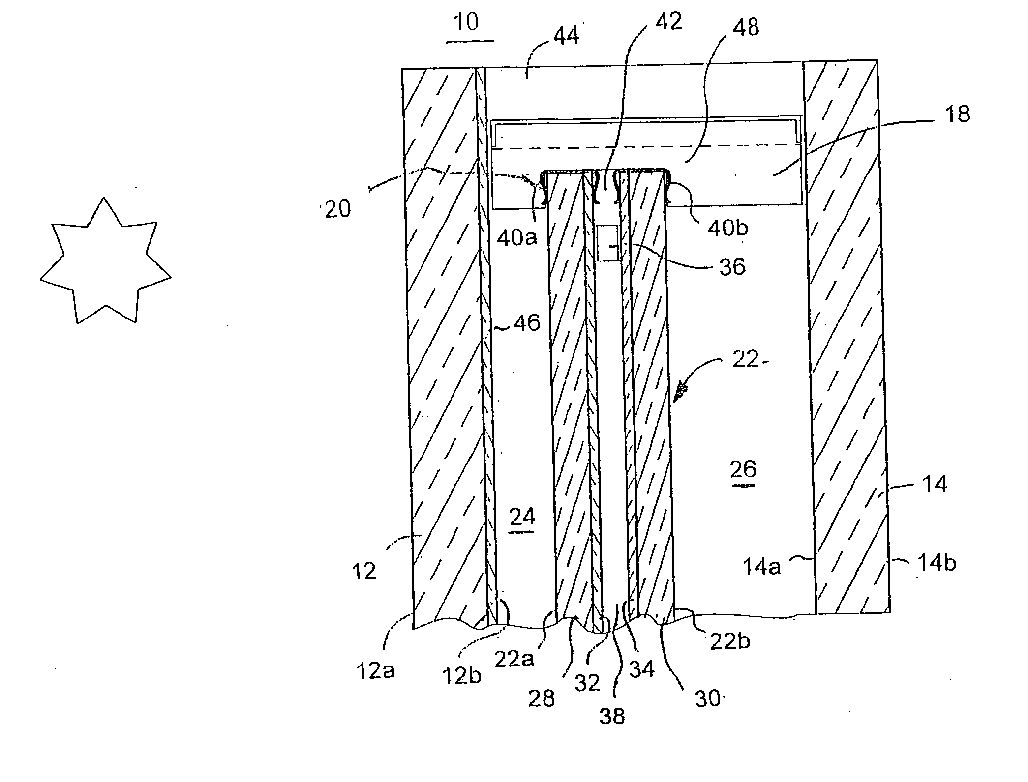
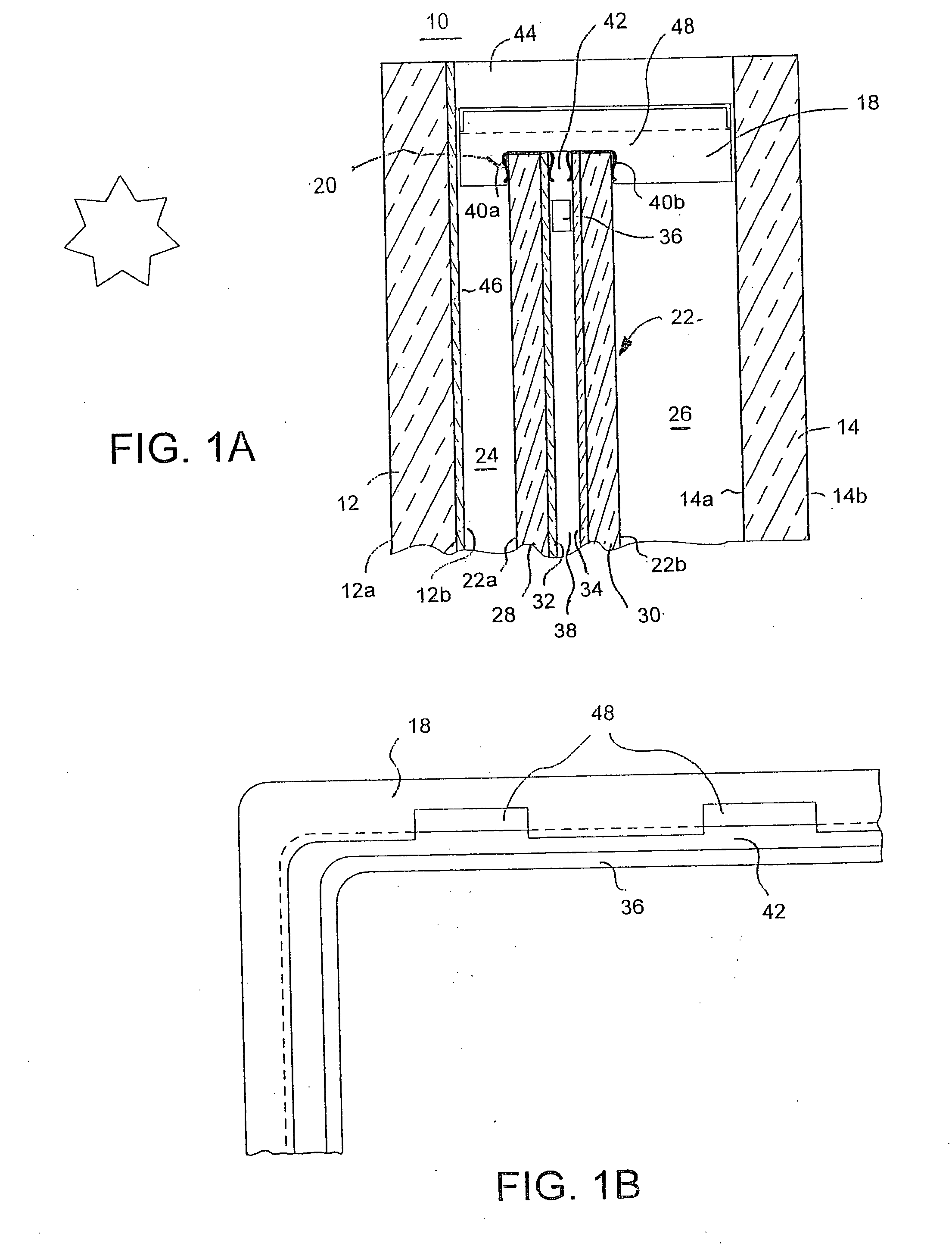
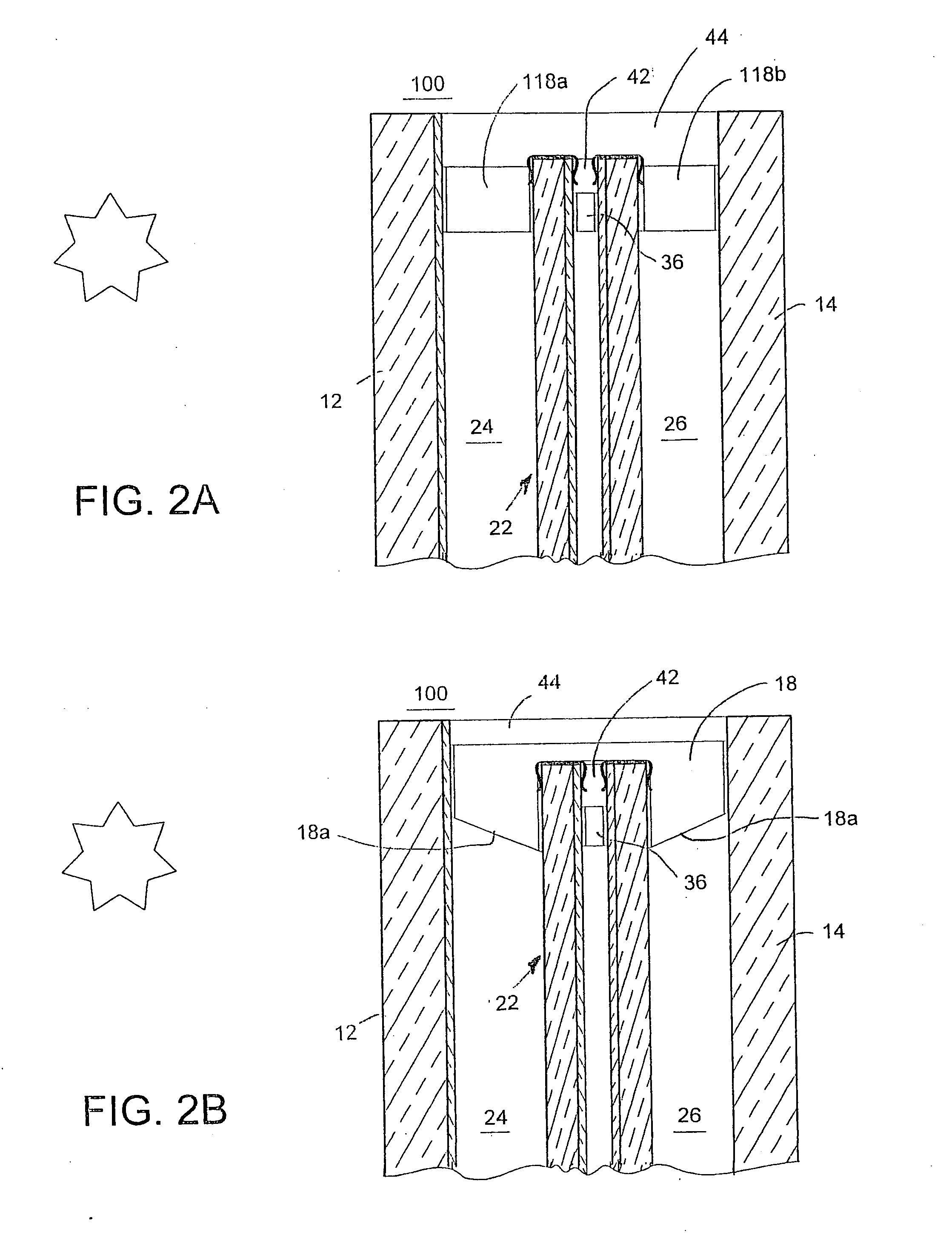
An electrochromic window assembly is disclosed that includes a first substrate and a second substrate that is maintained in a parallel and spaced relation from the first substrate by means of a window frame and spacer. The window assembly further includes an electrochromic device mounted within the airtight chamber formed between the first and second substrates. Electrochromic device 22 may be mounted so as to provide an air chamber between first substrate 12, which is the external substrate, and electrochromic device 22. At least one of the chambers formed between substrates 12 and 14 and electrochromic device 22 may be filled with an insulating gas such as argon. Also disclosed are novel methods for manufacture of an electrochromic device for incorporation into such a window assembly. A novel electrochromic device is also disclosed having electrical bus clips secured about the entire periphery of the electrochromic device.

Description

CROSS-REFERENCE TO RELATED APPLICATIONS [0001] This application is a divisional of U.S. patent application Ser. No. 10 / 713,792, filed on Nov. 14, 2003, now U.S. Pat. No. 6,842,276, which is a divisional of U.S. patent application Ser. No. 10 / 349,829, filed on Jan. 23, 2003, now U.S. Pat. No. 6,671,080, which is a divisional of U.S. patent application Ser. No. 09 / 989,619, filed on Nov. 20, 2001, now U.S. Pat. No. 6,594,067, which is a divisional of U.S. patent application Ser. No. 09 / 626,714, filed on Jul. 25, 2000, now U.S. Pat. No. 6,407,847, the entire disclosures of which are incorporated herein by reference.BACKGROUND OF THE INVENTION [0002] The present invention generally relates to windows having variable transmittance light filters, and more specifically to windows including electrochromic light filters. [0003] Variable transmittance light filters, such as electrochromic light filters, have been proposed for use in architectural windows, skylights, and in windows and sunroofs...

Claims


Application Information

Patent Timeline
Patent Type & Authority Applications(United States)
IPC IPC(8): E06B3/66E06B3/663E06B3/67E06B9/264G02F1/15G02F1/153G02F1/155G02F1/161
CPCE06B3/66E06B3/66366E06B3/6722E06B3/6775E06B9/264G02F2201/44G02F1/153G02F1/1533G02F1/155G02F1/161E06B2009/2464Y10S359/90
Inventor POLL, DAVID L.ASH, KEVIN L.THEISTE, DAVID A.GUARR, THOMAS F.TONAR, WILLIAM L.
Owner GENTEX CORP
Learn More