

Method and apparatus for bending resin tube
a technology of resin tubes and bending dies, which is applied in the field of methods and apparatus for bending resin tubes, can solve the problems of human assistance, difficult to automate the procedures for positioning resin tubes in the bending dies, and increase the cost of dies, so as to reduce thermal efficiency, prevent wastewater pollution, and increase the operating time
- Summary
- Abstract
- Description
- Claims
- Application Information
AI Technical Summary
Benefits of technology
Problems solved by technology
Method used
Image

Examples
Embodiment Construction
[0031] Embodiments of the method and apparatus for bending a resin tube according to the present invention as described in the foregoing shall be described in further detail hereunder with reference being made to the drawings.
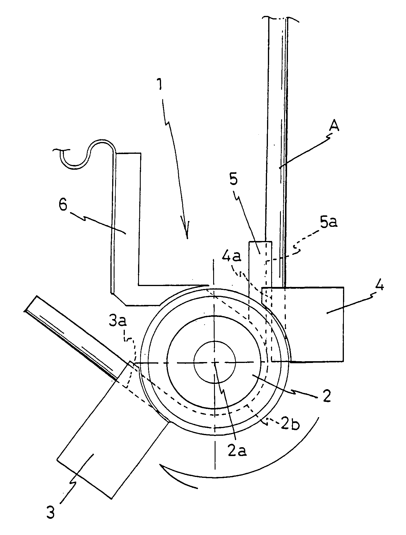
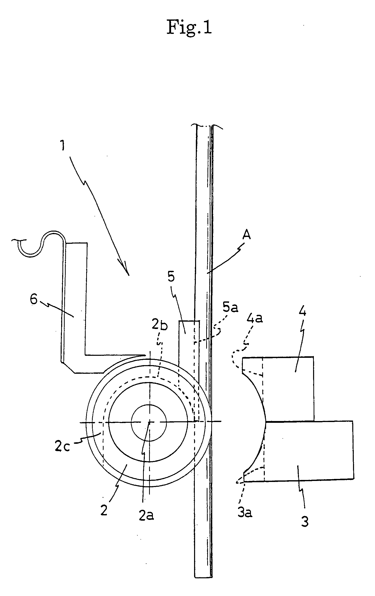
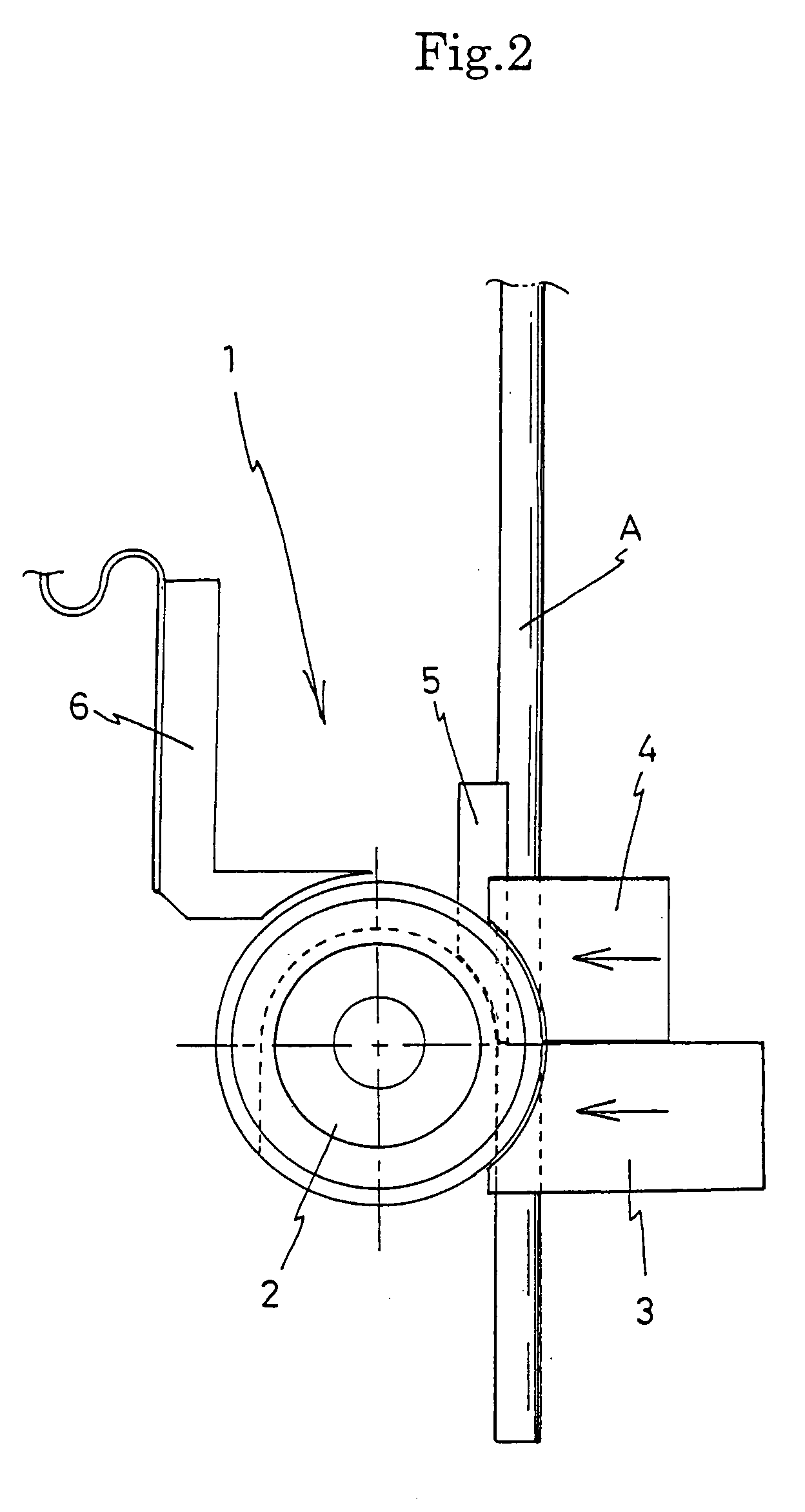
[0032]FIG. 1 is a plan view schematically showing an embodiment of the apparatus for bending a resin tube according to the present invention, FIGS. 2 through 7 are plan views showing the actions involved in bending a resin tube with the apparatus shown in FIG. 1, FIG. 8 is a cross-sectional view of the region along line A-A in FIG. 4, FIG. 9 is a cross-sectional view of the region along line B-B in FIG. 4, and FIG. 10 is a cross-sectional view of the region along line C-C in FIG. 4.
[0033] The bending apparatus 1 shown in the drawings is equipped with a bending die 2, a clamping die 3 for fixing a resin tube A in the bending die 2, a pressure die 4 for relatively moving the resin tube A along the bending die while pressing the tube against the bending die, a s...
PUM
| Property | Measurement | Unit |
|---|---|---|
| frequency | aaaaa | aaaaa |
| frequency | aaaaa | aaaaa |
| frequency | aaaaa | aaaaa |
Abstract
Description
Claims
Application Information