Organic luminescence device and its production method

a luminescence device and organic technology, applied in the manufacture of electrode systems, electric discharge tubes/lamps, discharge tubes luminescence screens, etc., can solve the problems of insufficient glass substrate in the luminescence device, very susceptible to the luminescence device, and insufficient gas-barrier capability of the glass substra

Inactive Publication Date: 2005-06-09
PANASONIC CORP
View PDF2 Cites 36 Cited by
  • Summary
  • Abstract
  • Description
  • Claims
  • Application Information

AI Technical Summary

Benefits of technology

[0006] The present invention has been achieved in order to solve the above-mentioned conventional problem, and its object is to provide an organic luminescence device using a substrate excellent in gas-barrier capability, and a method for producing the same.

Problems solved by technology

However, the organic luminescence device is very susceptible to the infiltration of oxygen, water vapor, etc. from outside, and the luminescence performance thereof is decreased immediately due to the infiltration.
However, even the glass substrate is insufficient in the organic luminescence device that requires a gas permeation amount of 0.01 g / m2 / 24 h or less (measuring limit or less).
However, there is a problem that the plastic substrate has a gas permeability for oxygen, water vapor, etc. larger than that of the glass substrate.
At present, it is very difficult to use the plastic substrate for the organic luminescence device.

Method used


Image

  • Organic luminescence device and its production method
  • Organic luminescence device and its production method

Examples


embodiment 1

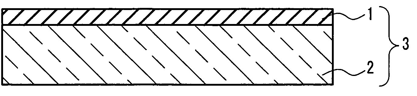
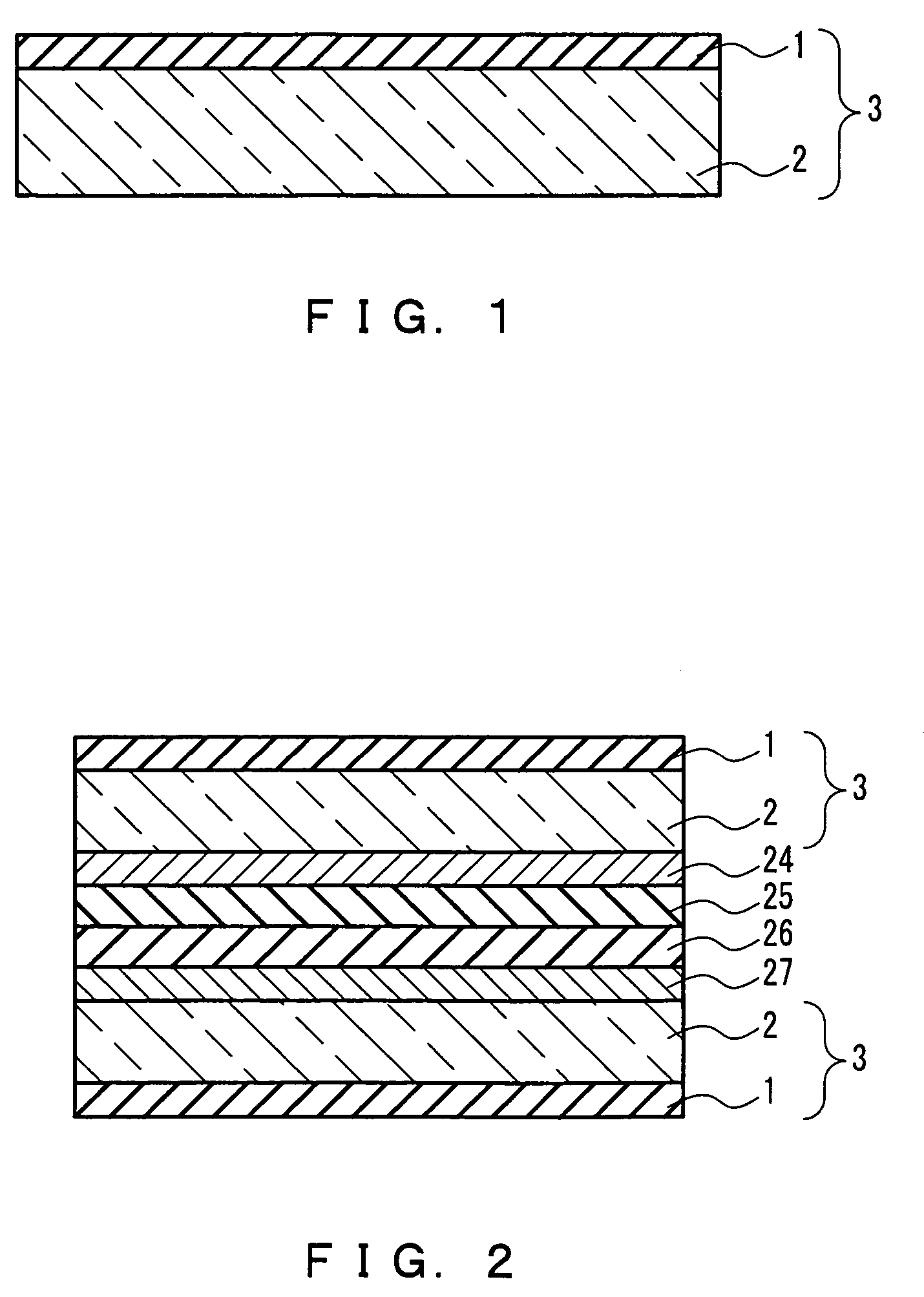
[0018]FIG. 1 is a cross-sectional view showing a substrate with a gas-barrier film of the present invention. In FIG. 1, reference numeral 1 denotes a gas-barrier film, 2 denotes a substrate, and 3 denotes a substrate with a gas-barrier film. Furthermore, FIG. 2 is a cross-sectional view showing an organic luminescence device of the present invention. In FIG. 2, reference numeral 24 denotes a negative electrode, 25 an organic luminescence layer, 26 denotes a hole transporting layer, and 27 denotes a positive electrode.

[0019] First, a gas-barrier film 1 (thickness: 150 Å) composed of silicon oxide that is an amorphous oxide, boron oxide, and titanium oxide was formed on one surface of the substrate 2 made of glass, using RF magnetron sputtering, whereby a substrate 3 with a gas-barrier film was produced. The RF magnetron sputtering was performed under the condition that a pellet of boron oxide and titanium oxide was placed on a target made of silicon oxide with the glass substrate 2 ...

embodiment 2

[0023] An organic luminescence device was produced in the same way as in Embodiment 1, except that a phosphorus oxide and a lead oxide were used in place of the boron oxide and the titanium oxide. The oxygen gas permeation amount of the substrate with a gas-barrier film was measured to be 0.01 g / m2 / 24 h or less (measuring limit or less).

[0024] In the gas-barrier film of the present embodiment, the phosphorus oxide and the lead oxide close gaps of the silicon oxide composed of a network structure, so that the permeation of gas is suppressed. Consequently, in the organic luminescence device using the substrate with a gas-barrier film of the present embodiment, oxygen, water vapor, etc. did not enter the device from outside, so that luminescence failures did not occur.

embodiment 3

[0025] An organic luminescence device was produced in the same way as in Embodiment 1, except that a sodium oxide and a barium oxide were used in place of the boron oxide and the titanium oxide. The oxygen gas permeation amount of the substrate with a gas-barrier film was measured to be 0.01 g / m2 / 24 h or less (measuring limit or less).

[0026] In the gas-barrier film of the present embodiment, the sodium oxide and the barium oxide close gaps of the silicon oxide composed of a network structure, so that the permeation of gas is suppressed. Consequently, in the organic luminescence device using the substrate with a gas-barrier film of the present embodiment, oxygen, water vapor, etc. did not enter the device from outside, so that luminescence failures did not occur.


PUM

PropertyMeasurementUnit
glass transition temperatureaaaaaaaaaa
atomic radiusaaaaaaaaaa
temperatureaaaaaaaaaa

Abstract

An organic luminescence device uses a substrate with a gas-barrier film in which a gas-barrier film containing an amorphous oxide and at least two kinds of oxides selected from the group consisting of boron oxide, phosphorus oxide, sodium oxide, potassium oxide, lead oxide, titanium oxide, magnesium oxide, and barium oxide is formed on a substrate. The selected two kinds of oxides are a combination of an oxide of an element having a large atomic radius and an oxide of an element having a small atomic radius. The substrate is made of glass or plastic. As a result, the organic luminescence device using a substrate excellent in gas-barrier capability to prevent the infiltration of oxygen, water vapor, etc. from outside is provided.

Description

TECHNICAL FIELD [0001] The present invention relates to an organic luminescence device using a substrate with a gas-barrier film, and a method for producing the same. BACKGROUND ART [0002] Electroluminescence (EL) panels have characteristics of high visibility, excellent display ability, and capability of high-speed response, and hence, are expected as a future display apparatus for electronic equipment, etc. Therefore, recently, an organic luminescence device used for an EL panel has been studied actively. [0003] In general, the organic luminescence device has a configuration in which an organic luminescence layer containing a fluorescent compound is interposed between a negative electrode and a positive electrode disposed on a glass substrate. When electrons and holes are injected to the organic luminescence layer to be recombined, excitons are generated, and light is emitted when the excitons are deactivated. [0004] However, the organic luminescence device is very susceptible to ...

Claims


Application Information

Patent Timeline
Patent Type & Authority Applications(United States)
IPC IPC(8): B32B9/00H05B33/04C03C17/02H01L51/50H01L51/52H05B33/02H05B33/10
CPCH01L51/5237H10K50/844H05B33/04H05B33/14H05B33/10H05B33/02
Inventor SATANI, HIROSHI
Owner PANASONIC CORP
Why Eureka
Try Eureka