Signal reception device, signal reception circuit, and reception device

a signal reception and signal technology, applied in the direction of high frequency circuit adaptation, color signal processing circuit, television system, etc., can solve the problems of mutual interference in the high frequency range, serious electromagnetic interference, and insufficient space between the tuners in many cases, so as to reduce the cost of products, reduce the effect of mutual interference, and reduce the effect of performance degradation

Inactive Publication Date: 2005-06-09
SONY CORP
View PDF9 Cites 13 Cited by
  • Summary
  • Abstract
  • Description
  • Claims
  • Application Information

AI Technical Summary

Benefits of technology

[0027] Another object of the present invention is to provide a signal receiving apparatus and a signal receiving circuit that reduce, with a simple structure, mutual interference generated when a plurality of tuners operate at a time.
[0028] Still another object of ...

Problems solved by technology

In this case, mutual interference in high frequency range is caused due to simultaneous use of the tuner circuits.
Since the tuners are attached to the back panel side of a so-called set-top box (STB) in general, sufficient space cannot be assured between the tuners in many cases.
Accordingly, magnetic field or electric field generated from the respective tuner circuits affects other tuner circuits, which may cause serious electromagnetic interference such as cochannel interference.
Shielding of the tuner units using the shield case or the like as described above increases the number of components, which may lead to an increased product cost.
This may prevent effective arrangement of the tuner units in the set-top box.
The high frequency current that has been propagated through t...

Method used


Image

  • Signal reception device, signal reception circuit, and reception device
  • Signal reception device, signal reception circuit, and reception device
  • Signal reception device, signal reception circuit, and reception device

Examples


Embodiment Construction

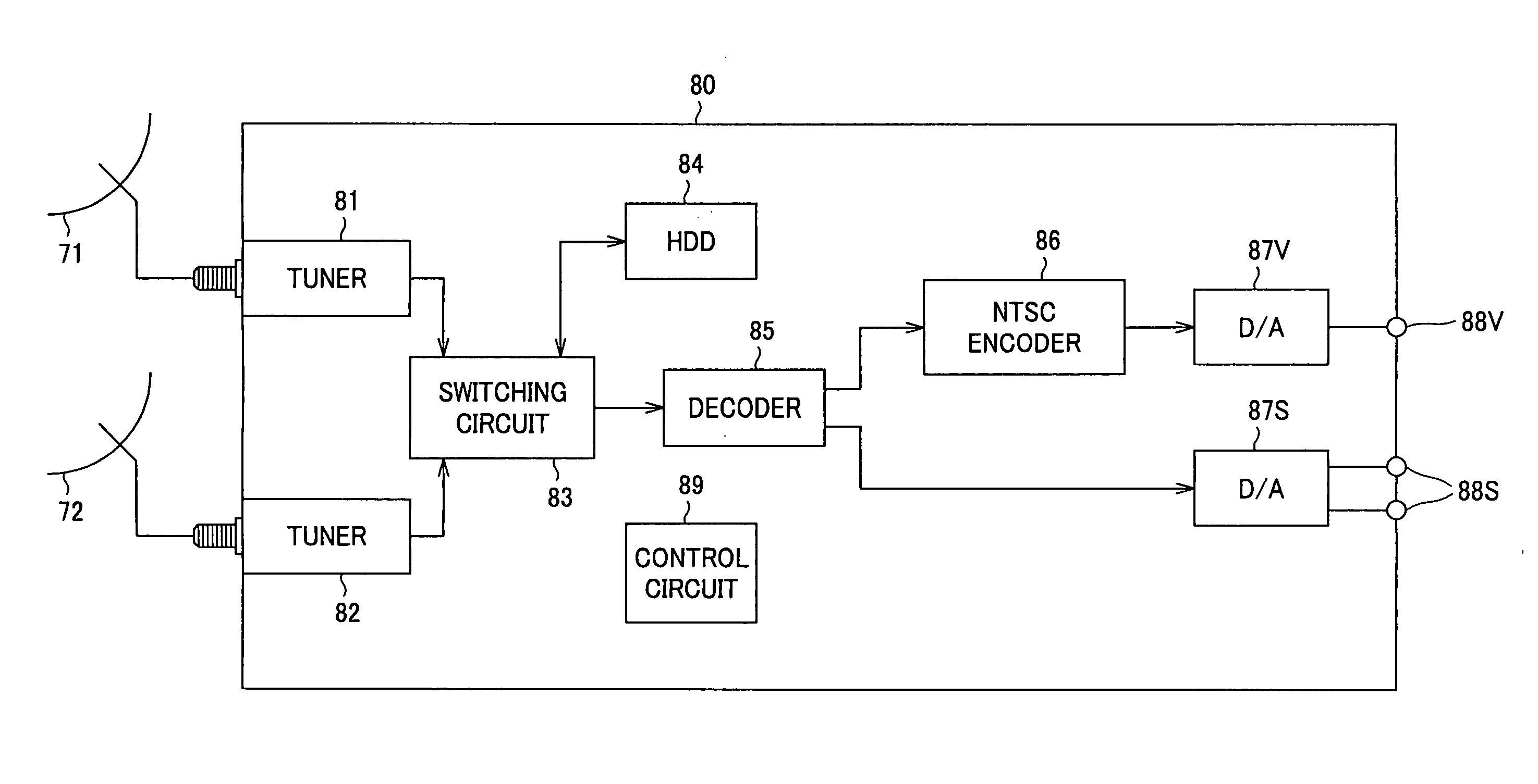
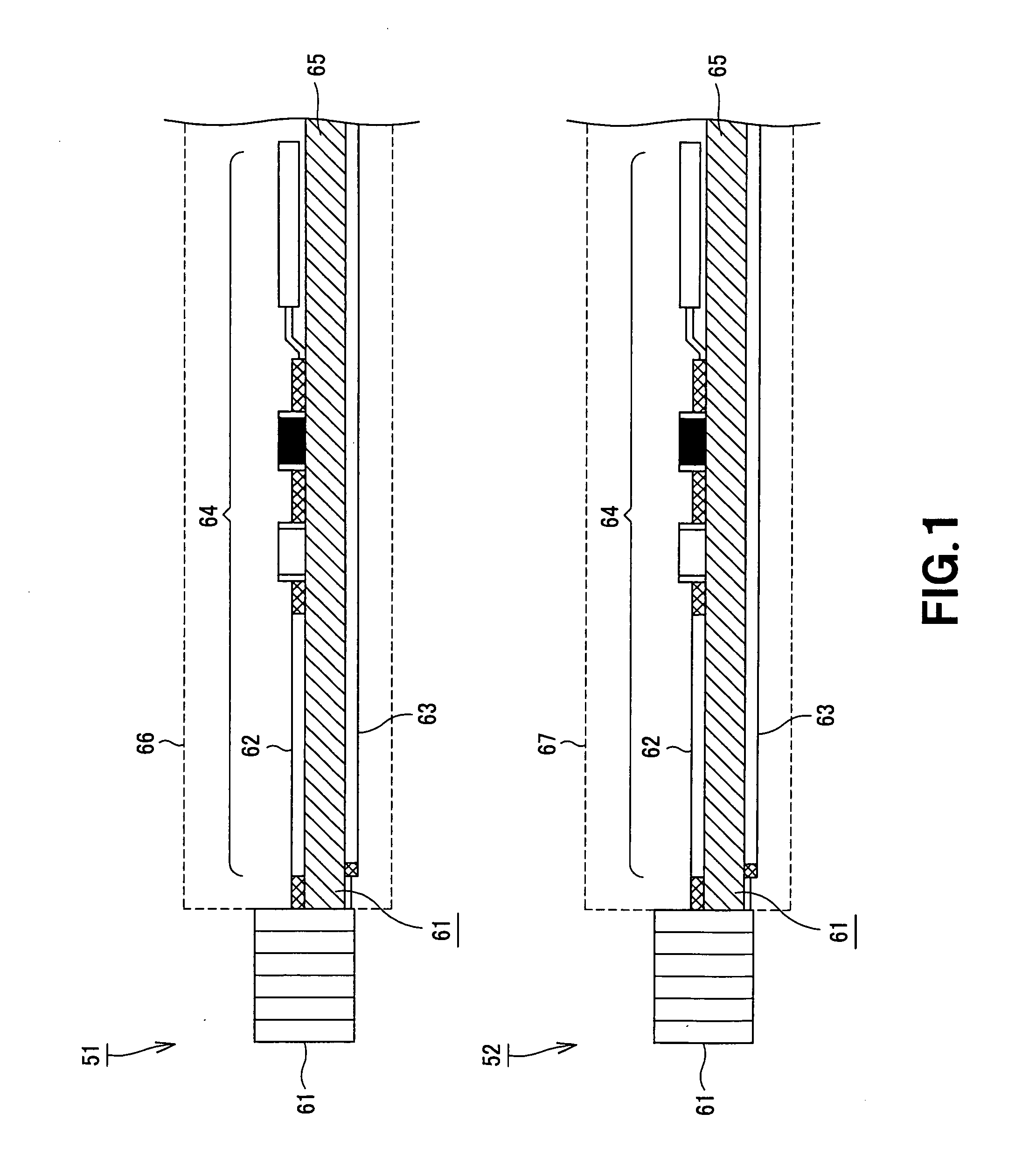
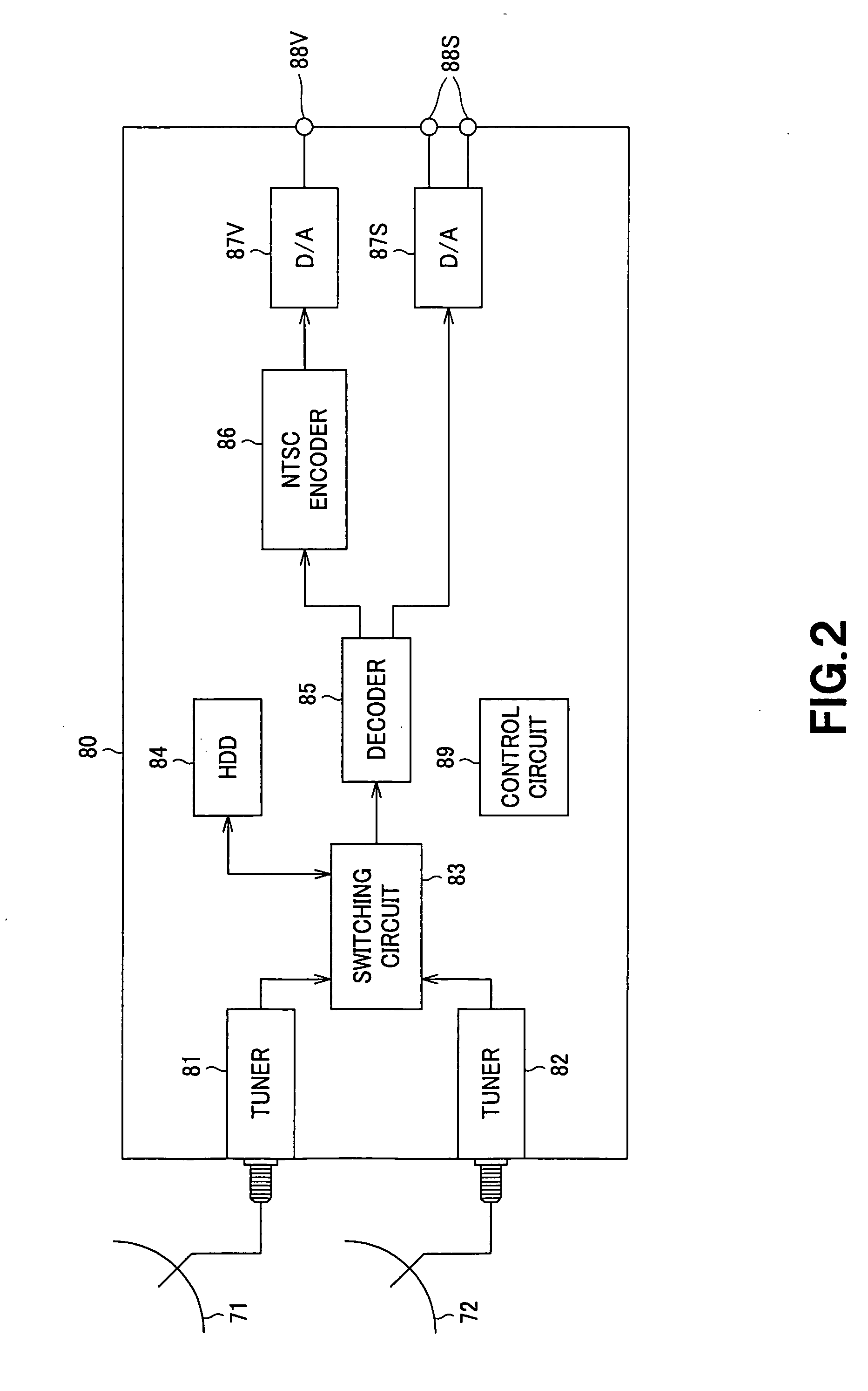
[0051] A tuner circuit and a signal receiving apparatus including the tuner circuit to which the present invention is applied will be described in detail with reference to the accompanying drawings.

[0052]FIG. 5 is a side view showing a base plate of a tuner circuit 1 to which the present invention is applied. The tuner circuit 1 is a circuit board in which circuits for receiving signals are designed, according to a microstripline structure, on a multilayer board. The tuner circuit 1 receives broadcast waves that have been modulated in a predetermined format, and demodulates the received waves. The tuner circuit 1 shown here includes a circuit configuration for receiving, for example, DVB-S (Digital VideoBroadcast-Satellite).

[0053] The tuner circuit 1 includes an input terminal 11 to which a broadcast wave in which a video signal and / or an audio signal are modulated in a predetermined format is input, and a mount layer 13 on which a main circuit 12 for selecting, from the broadcast...


PUM


Abstract

The present invention provides a receiver that includes a plurality of tuners for receiving broadcasts such as satellite broadcast. A tuner circuit (1) includes an input terminal (11) for inputting a broadcast wave in which a video signal and/or an audio signal are modulated in a predetermined format, and a mount layer (13) on which a main circuit (12) for selecting, from the broadcast wave, a video signal and/or an audio signal included in a predetermined frequency band is mounted. In the tuner circuit (1), a first ground layer (15) is disposed, through a first dielectric layer (14), on the surface opposite to that on which the main circuit (12) of the mount layer (13) is arranged, and a second ground layer (17) is disposed through a second dielectric layer, thereby suppressing mutual interference between tuners.

Description

TECHNICAL FIELD [0001] The present invention relates to a signal receiving apparatus and a signal receiving circuit, and more particularly, to a signal receiving apparatus that receives at least one broadcast wave by means of a plurality of receiving circuits or receives broadcast waves by means of corresponding receiving circuits, a signal receiving circuit that is effectively employed in the signal receiving apparatus, and a receiver having a plurality of built-in tuners. [0002] The present application claims priority from Japanese Patent Application No. 2002-104756 filed on Apr. 8, 2002, and Japanese Patent Application No. 2002-127415 filed on Apr. 26, 2002, entire contents of which are hereby incorporated by reference into this application. BACKGROUND ART [0003] Apparatuses that manage video or audio contents as digital data are now being widely used, and correspondingly, TV broadcast also becomes increasingly digitalized. The more increased number of channels can be provided in...

Claims


Application Information

Patent Timeline
IPC IPC(8): H04B1/08H04B1/18H04N5/50H04N5/64H05K1/02H05K1/14
CPCH04B1/005H04B1/08H04B1/18H04N5/50H04N5/64H05K1/0218H04N21/6143H05K1/144H05K9/006H05K2201/043H05K2201/0715H05K2201/0723H04N21/4263H05K1/0237
Inventor KAWAKAMI, SATORUIMAI, TADASHI
Owner SONY CORP
Why Eureka
Try Eureka