Circular polarized light method and device for determining wall thickness and orientations of fibrils of cellulosic fibres

a cellulosic fibre and polarized light technology, applied in the field of polarized light, optical and all related physical properties of birefringent specimens, can solve the problems of difficult fibril angle, many difficulties in direct imaging techniques for accurate measurement of fibre wall thickness

Active Publication Date: 2005-06-09
FPINNOVATIONS INC
View PDF13 Cites 39 Cited by
  • Summary
  • Abstract
  • Description
  • Claims
  • Application Information

AI Technical Summary

Benefits of technology

[0028] A particular advantage of the present invention is that it is not necessary to position or orient the specimen relative to the circular polarized light beam in which it is disposed. Similarly, it is not necessary to adjust, for example by rotation, the analyzer of the emergent light.
[0029] The specimen is thus in a non-restricted orientation in the beam.
[0030] Thus, in one embodiment, this invention provides a new polarized-light method as the solution for determining both the phase retardations of multi-layered birefringent specimens at different wavelengths and the orientations of their optical axes, especially the wall thickness and fibril angle of wood pulp fibres.
[0031] The number of individual wavelengths needed in the system de

Problems solved by technology

Unfortunately, due to the microscopic size of fibres, both fibre wall thickness and fibril angle are difficult to measure.
Moreover, all fibre properties are heterogeneous in nature.
However, this direct imaging technique faces many difficulties for accurate measurements of fibre wall thickness, which varies greatly from less than one μm to several μm.
Recent investigation has shown that fibre wall thickness measurements from the Kajaani FibreLab are grossly incorrect [7].
Although this technique provides valuable information on fibre transverse dimensions and is a good research tool, it is too slow for most practical industrial purposes.
Thus, a rapid and accurate technique for measuring the wall thickness of individual wood pulp fibres is still lacking.
Although these techniques can provide measurements on fibril angles, they are also very slow.
However, this procedure requires a single wall; it cannot be used for intact fibres, as the opposite wall of the helicall

Method used


Image

  • Circular polarized light method and device for determining wall thickness and orientations of fibrils of cellulosic fibres
  • Circular polarized light method and device for determining wall thickness and orientations of fibrils of cellulosic fibres
  • Circular polarized light method and device for determining wall thickness and orientations of fibrils of cellulosic fibres

Examples


Embodiment Construction

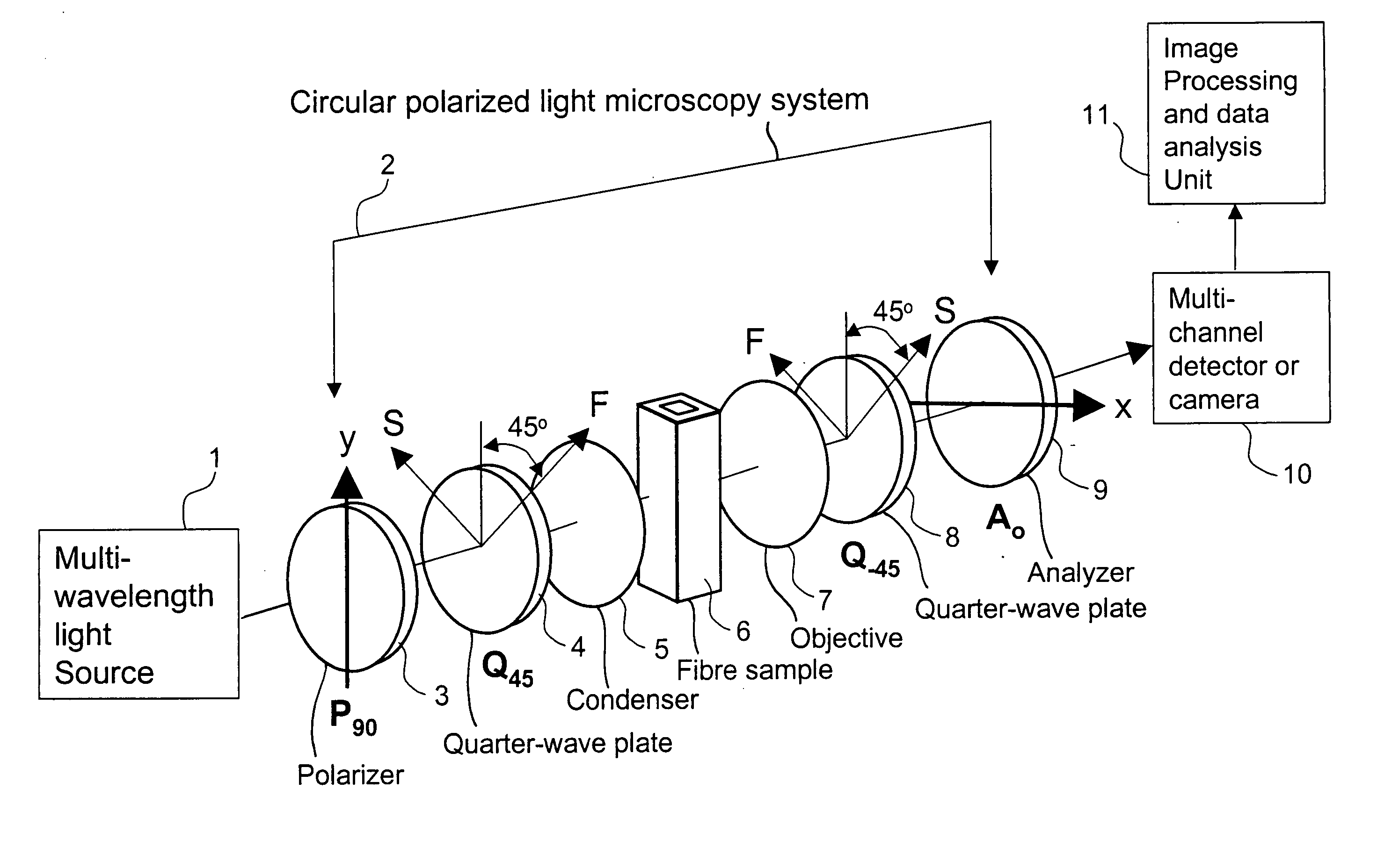
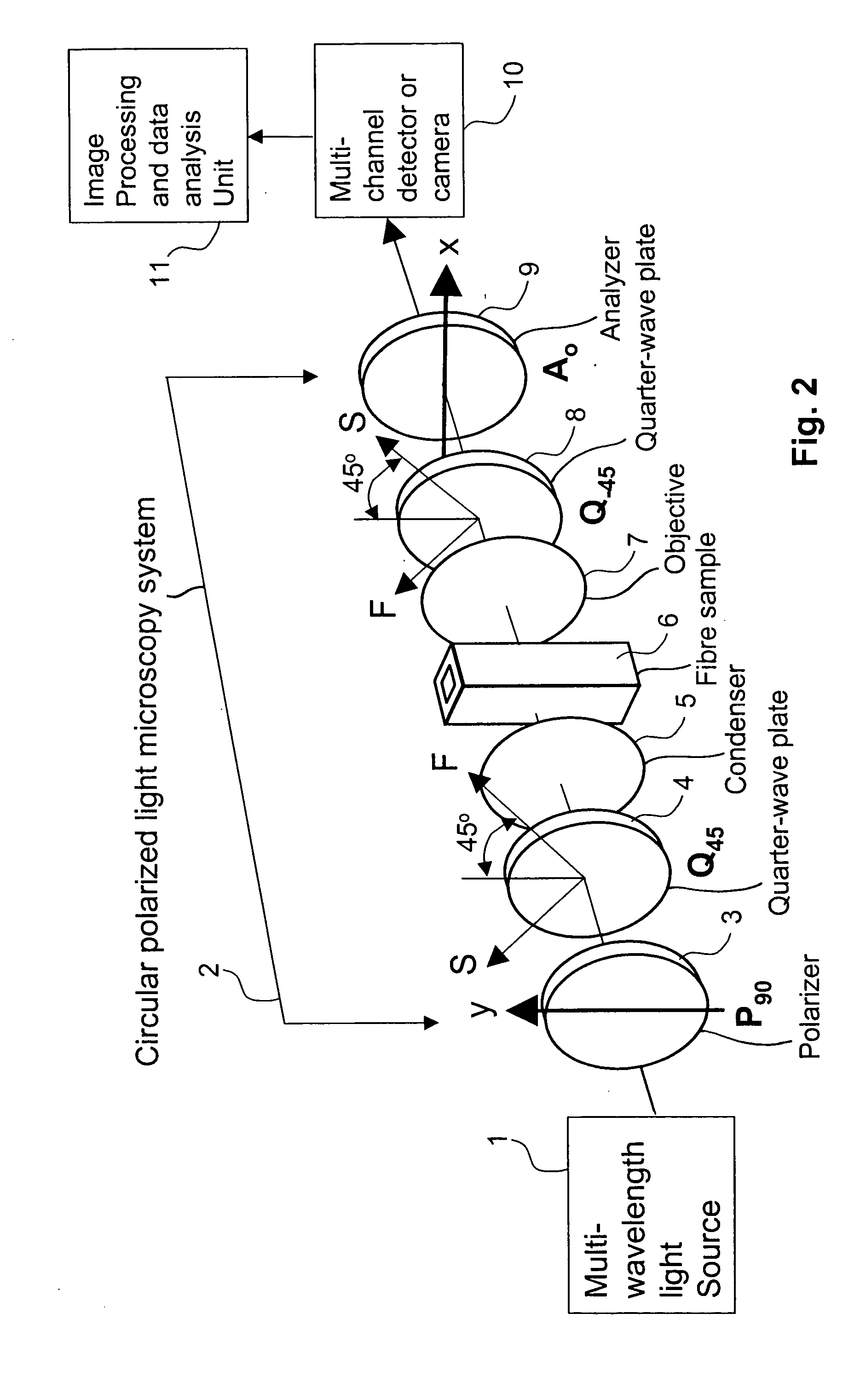
[0020] The method of the invention may be carried out with the circular polarized light in a dark field or a bright field.

[0021] The light source is typically of multiple predetermined and well-defined wavelengths, and the number of predetermined wavelengths is suitably at least the same as the number of parameters, to be determined.

[0022] The method may suitably be employed to determine the relative phase retardations, or the orientations of the optical axes of the specimen, or both.

[0023] The circular polarized light system employed is suitably comprised of a polarizer and an analyzer; both the polarizer and the analyzer may be linear polarizers; and a pair of well-matched achromatic quarter-wave retarders with a working wavelength range covering all predetermined wavelengths of the light source. The optical axes of the retarders are oriented 90° to each other and 45° to the polarizer and the analyzer.

[0024] The apparatus suitably includes, for determining light intensities of...


PUM


Abstract

This invention provides a novel, rapid method and device for determining the relative phase retardation of a multi-layered specimen, which is related to the thicknesses of its layers and walls, and the orientations of its optical axes. An intact wood pulp fibre is a typical multi-layered birefringent specimen. This new method is based on the change of polarization of polarized light that passes through a specimen composed of birefringent layers with different optical axis orientations, such as directions of cellulosic microfibrils oriented differently in various layers of wood fibres. In particular, a novel solution is found to relate the emerging light intensity from an intact wood fibre to the incident light intensity, the wavelength of the light, and the relative phase retardations of various layers and orientations of their cellulosic microfibrils, such as fibril angle, in a circular polarized light system. This new method evaluates the transmitted light intensities of multiple predetermined wavelengths simultaneously to determine the optical and physical properties of a multi-layered specimen being measured. A device for determining the relative phase retardation (retardance) of fibre walls and the fibril angle of intact wood fibres in accordance with the presented invention comprises a light source with well defined multi-wavelengths, an achromatic circular polarized light system, appropriate imaging optics, a multi-channel camera such as a digital color camera that has two or more wavelength (color) detection channels, and an image processing and data analysis system. The measurements take advantage of the birefringence of cellulosic microfibrils, and thus require neither sample preparation nor high resolution optics. Specimen alignment is not required as specimens such as wood fibres are evaluated under circular polarized light. Compared with other methods, this invention is more rapid, accurate, and robust. This method can be automated, and implemented in a fibre flow-through system, thus allowing a rapid assessment of wood pulp fibre properties (on-line in real time).

Description

CROSS-REFERENCE TO RELATED APPLICATION [0001] This application claims priority under 35 U.S.C. 119(e) from U.S. Provisional Application Ser. No. 60 / 526,280, filed Dec. 3, 2003.BACKGROUND OF THE INVENTION [0002] i) Field of the Invention [0003] The present invention relates to polarized light, optical and all related physical properties of a birefringent specimen, and in particular, to a polarized light method and device for determining the relative phase retardations, and the orientations of the optical axes of different layers in a multi-layered birefringent specimen, preferably, the relative phase retardation, which is related to the wall thickness, and the fibril angle of intact wood pulp fibres. [0004] ii) Description of the Prior Art [0005] A wood fibre, an example of a cellulosic fibre, is a biological material consisting of four principal layers: the primary wall P1, and the three secondary wall layers S1, S2 and S3 as shown in FIG. 1(a) [1]. All three secondary layers are co...

Claims


Application Information

Patent Timeline
IPC IPC(8): G01B11/06G01B11/26G01J4/00G01N21/21G01N21/23G01N21/41G01N21/86G01N33/34G01N33/46
CPCG01B11/0641G01B11/26G01N2021/8681G01N33/46G01N2021/216G01N21/23
Inventor JANG, HO FAN
Owner FPINNOVATIONS INC
Why Eureka
Try Eureka