Surface modification of ePTFE and implants using the same

a technology applied in the field of surface modification of eptfe and implants using the same, can solve the problems of physiological decay in biological activity, decrease of graft patency, and inability to support endothelialization in vivo

Inactive Publication Date: 2007-03-01
LIFESHIELD SCI
View PDF7 Cites 68 Cited by
  • Summary
  • Abstract
  • Description
  • Claims
  • Application Information

AI Technical Summary

Benefits of technology

[0021] In another aspect of the present invention, an implanted, surface modified ePTFE graft includes ePTFE having a node and fibril structure and having a carburized surface formed by plasma immersion ion implantation without destroying the node and fibril structure and having cellular material attached to the fibrils or attached to functional groups covalently bonded to the fibrils and substantially covering and / or filling the nodes. The carburized surface desirably has a depth of about 30 nm to about 500 nm.

Problems solved by technology

When this occurs, a graft is occluded by such thrombotic material, which in turn, results in decreased patency for the graft.
Heparin, however, has the problem of a physiological decay in biological activity and in some cases iatrogenic inactivation with protaminsulfate.
Endothelial cells as the inner lining of blood vessels are known to provide a hemocompatible surface. ePTFE as such, however, does not support endothelialization in vivo.
While, improved cell adherence and proliferation for RF plasma treated ePTFE was reported as compared to the non-treated ePTFE, long term stability of the cell layer and the long term stability of the plasma treatment were not adequate because plasma treatment usually only has a relatively short term effect as the modified molecules tend to migrate into the bulk of the polymer.
Such high energy levels, however, were reported in Yotoriyama to destroy the fibrils of the ePTFE.

Method used


Image

  • Surface modification of ePTFE and implants using the same
  • Surface modification of ePTFE and implants using the same
  • Surface modification of ePTFE and implants using the same

Examples


examples

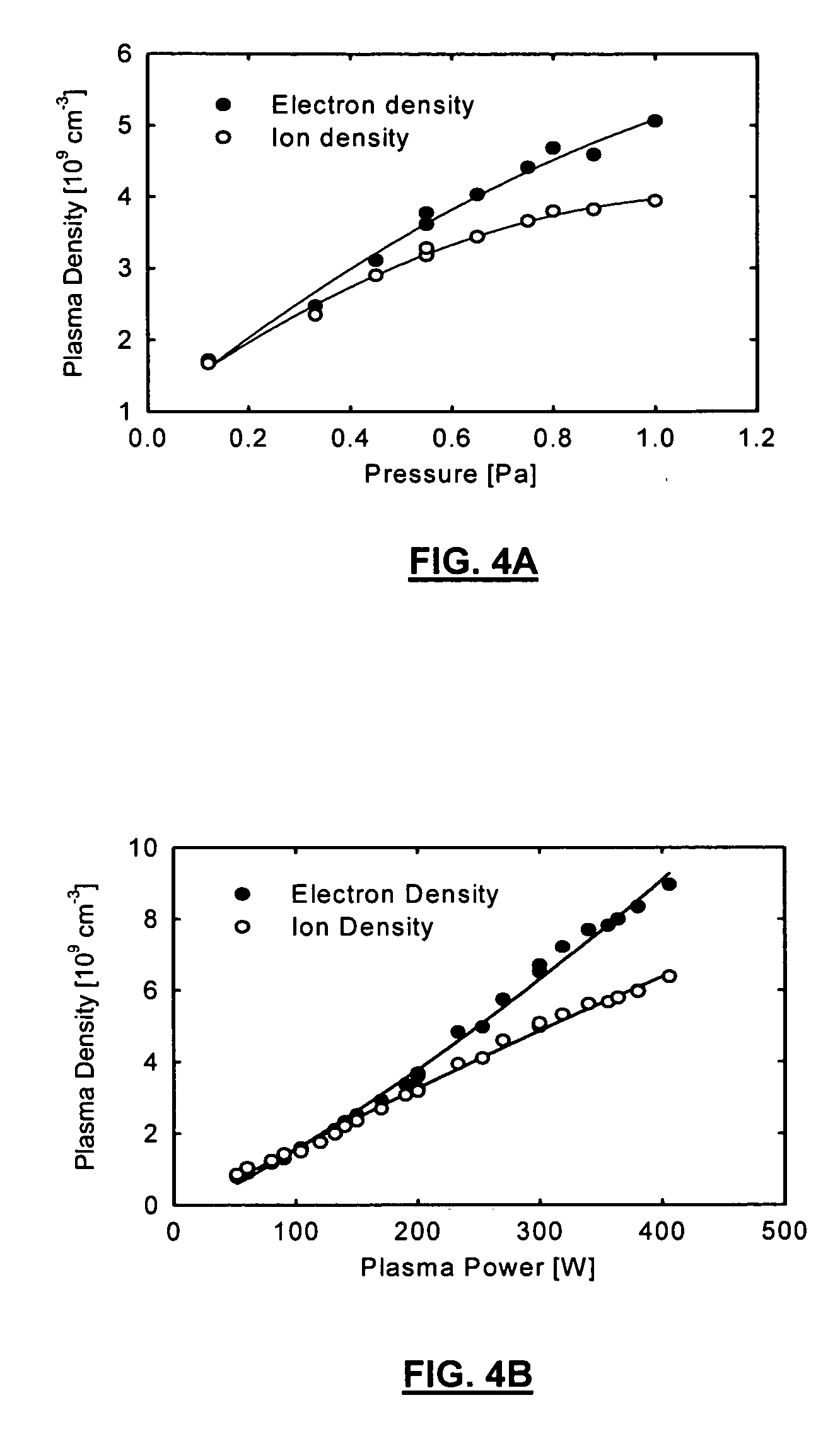
[0070] Plasma immersion ion implantation of nitrogen, oxygen and argon ions with different energies and different regimes of treatment was used for the modification of ePTFE sheets, PTFE thin films and low-density polyethylene (LDPE) films. The PTFE and LDPE samples were used as satellite samples for supporting analysis.

[0071] Materials and Methods

[0072] Materials

[0073] ePTFE provided by Boston Scientific SCIMED was used for plasma immersion ion implantation treatment, structure analysis and for cell culture experiments. PTFE films of 20 μm and LDPE films of 50 μm were used for plasma immersion ion implantation treatment and structure analysis. The PTFE and LDPE films were cleaned by alcohol before plasma immersion ion implantation. The ePTFE samples were not cleaned before plasma immersion ion implantation, but the surface of the samples was not touched after removing from the packing.

[0074] Plasma immersion ion implantation

[0075] Most of the modifications were done with the e...


PUM

PropertyMeasurementUnit
poweraaaaaaaaaa
pressureaaaaaaaaaa
depthaaaaaaaaaa

Abstract

A method for modifying an ePTFE surface by plasma immersion ion implantation includes the steps of providing an ePTFE material in a chamber suitable for plasma treatment; providing a continuous low energy plasma discharge onto the sample; and applying negative high voltage pulses of short duration to form a high energy ion flux from the plasma discharge to generate ions which form free radials on the surface of the ePTFE material without changing the molecular and/or physical structure below the surface to define a modified ePTFE surface. The step of applying the high voltage pulses modifies the surface of the ePTFE without destroying the node and fibril structure of the ePTFE, even when the step of applying the high voltage pulses etches and/or carburizes the surface of the ePTFE. The modified surface may have a depth of about 30 nm to about 500 nm. The ions are dosed onto the ePTFE sample at concentrations or doses from about 1013 ions/cm2 to about 1016 ions/cm2.

Description

CROSS-REFERENCE TO RELATED APPLICATIONS [0001] This application claims the benefit of U.S. Provisional Application No. 60 / 709,257, filed Aug. 18, 2005, the contents of which are incorporated herein by reference.FIELD OF THE INVENTION [0002] The present invention relates to surface modification of ePTFE and implants using the same. More particularly, the present invention relates to modification of ePTFE by plasma immersion ion implantation and fuctionalization of the modified ePTFE. BACKGROUND OF THE INVENTION [0003] An intraluminal prosthesis is a medical device used in the treatment of diseased bodily lumens. One type of intraluminal prosthesis used in the repair and / or treatment of diseases in various body vessels is a stent. A stent is a generally longitudinal tubular device formed of biocompatible material which is useful to open and support various lumens in the body. For example, stents may be used in the vascular system, urogenital tract, esophageal tract, tracheal / bronchial...

Claims


Application Information

Patent Timeline
Patent Type & Authority Applications(United States)
IPC IPC(8): A61F2/06
CPCA61L27/16A61L27/38C08J2327/18C08J7/123B29L2031/7532A61L27/54A61L31/005A61L31/048A61L31/16A61L2300/606A61L2400/18B05D3/144B29C59/14B29C59/142B29K2027/18C08L27/18
Inventor KONDYURIN, ALEXEYMAITZ, MANFRED FRANZ
Owner LIFESHIELD SCI
Why Eureka
Try Eureka