Process for the introduction of additives, into polymer melts

a technology of additives and polymer melts, applied in the direction of flow mixers, rotary stirring mixers, mixers, etc., can solve the problems of additives, catalysts or inhibitors having a corrosive effect at high temperatures on the materials employed in the apparatus and equipment in which the products are used, and experiencing undesirable changes. , to achieve the effect of advantageous material properties

Inactive Publication Date: 2005-06-09
BAYER MATERIALSCIENCE AG
View PDF10 Cites 14 Cited by
  • Summary
  • Abstract
  • Description
  • Claims
  • Application Information

AI Technical Summary

Problems solved by technology

The person skilled in the art knows that many additives, catalysts or inhibitors in pure form at the temperatures at which they are metered into the polymer melt may themselves experience undesirable changes such as chemical decomposition or decrease in desired properties.
Also, additives, catalysts, or inhibitors may at high temperatures have a corrosive effect on the materials employed in the apparatus and equipment in which the products are handled, especially at high concentrations and before they are mixed with the melt.
An additive, catalyst or inhibitor is regarded as corrosive if, in the case of the materials that are normally used in the process and from which the plant parts are fabricated, it causes erosion of 0.1 mm / year or more due to chemical attack, and also produces stress cracks or pitting.
A disadvantage is that an inertisation is possible only with high technical expenditure.
In addition the metering of solids is susceptible to interference and is not always sufficiently accurate or constant.
The temperature level is fixed to that of the main stream, with the result that harmful reactions of the additives may occur at this temperature.
The disadvantage of this process is the unavoidable increase in the extruder of the temperature of a part of the main stream, which on the one hand may adversely affect the quality of the polymer and in turn allow undesirable secondary reactions of the additive components, of the additive components with one another or of the additive components with the polymer of the side stream and / or of the main stream.
All the above possibilities have the disadvantage that the additives, catalysts or inhibitors are in contact in concentrated form at high temperatures with the walls of the apparatus parts and then reach the polymer melt, whereby they suffer damage and therefore can no longer exert the full desired effect in the polymer.
This therefore often results in thermal damage to the additives, with discolorations or even carbonization and thus blockages.
In addition the counter-pressures from the polymer melt region are often very high and variable, so that a clean and constant metering of the additives is difficult.
The high thermal stress experienced by the additives, catalysts or inhibitors as well as the interference in the metering lead to significant losses of quality and deterioration of the products to be produced.
The renewed melting of polymer granules adversely affects the quality as a rule and is therefore disadvantageous.
A further disadvantage is that the master batch has to be remelted in order to be introduced into the polymer.

Method used


Image

  • Process for the introduction of additives, into polymer melts
  • Process for the introduction of additives, into polymer melts
  • Process for the introduction of additives, into polymer melts

Examples


example 1

a) Preparation of Polycarbonate Melt

[0114] 8,600 kg / hour of melt mixture consisting of 4,425 kg of diphenyl carbonate / hour (20,658 mole / hour) and 4,175 kg of bisphenol A / hour (18,287 mole / hour) are pumped from a receiver, with the addition of 0.52 kg of the phenol adduct of tetraphenylphosphonium phenolate with 65.5% tetraphenylphosphonium phenolate / hour (0.786 mole / hour; i.e. 0.0043 mole %) dissolved in 4.5 kg of phenol / hour, through a heat exchanger, heated to 190° C., and fed through a residence column at 12 bar and 190° C. The mean residence time is 50 minutes. The melt is then passed through a pressure release valve into a separator under a pressure of 200 mbar. The discharged melt is reheated to 189° C. in a falling film evaporator, likewise under a pressure of 200 mbar, and collected in a receiver. After a residence time of 20 minutes the melt is pumped into the next three, similarly constructed, stages. The conditions in the 2nd / 3rd / 4th stage are 100 / 74 / 40 mbar; 218 / 251 / 27...

example 2

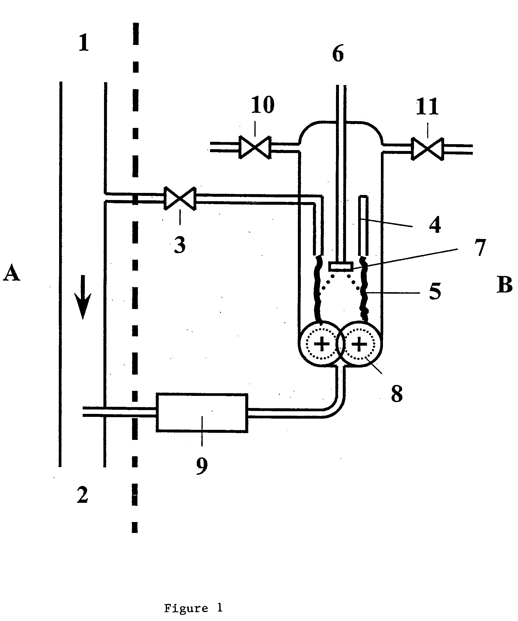
[0126] A polycarbonate melt stream of 4,600 kgihour to which phosphoric acid has previously been added as in Example 1 and in which the residual monomers were reduced, is mixed with GMS (mixture of glycerol monopalmitate and glycerol monostearate) according to the process of the present invention in order to improve the mold release behavior. To this end 150 kg of polycarbonate melt / hour at 287° C. are fed from the melt line under pressure behind the production unit and through a valve to an annular nozzle of 200 mm diameter, which is located centrally in a heated pressure vessel on the floor of which is arranged a gear-type pump. 1,475 g of GMS / hour are fed from above through an externally thermally insulated lance thermostatically controlled at 90° C., at the end of which is arranged a rotating plate atomiser. The plate atomiser is introduced sufficiently far so that the sprayed GMS melt impacts only on the melt stream that is formed. Nitrogen for example is fed through a valve in...


PUM

PropertyMeasurementUnit
erosionaaaaaaaaaa
temperatureaaaaaaaaaa

Abstract

A process for making a thermoplastic molding composition comprising (i) forming a vertically falling stream of molten polymer, and (ii) bringing at least one additive in solid or liquid states, in solution, in the form of a dispersion or in suspension into contact with at least a part of the surface of said stream and to introduce the additive in said stream to produce combined stream, and (iii) introducing the combined stream into a pump to form a pre-mix and (iv) introducing the premix into a mixer to form a homogeneous polymer melt. The entraining stream is then introduced to a pump to form a pre-mix which is then introduced to a mixer to form a homogeneous polymer melt. The process results in a compositions having advantageous material properties.

Description

FIELD OF THE INVENTION [0001] The invention relates to a process for preparation of thermoplastic molding compositions and more specifically to compositions that contain any of additives, catalysts or inhibitors. BACKGROUND OF THE INVENTION [0002] There are numerous reasons why polymer melts should be mixed with additives. Such additives may improve properties of the polymers such as for example resistance to degradation (additives), may promote desired reactions for the further production or processing procedure (catalysts), or may suppress undesirable reactions (inhibitors). [0003] The person skilled in the art knows that many additives, catalysts or inhibitors in pure form at the temperatures at which they are metered into the polymer melt may themselves experience undesirable changes such as chemical decomposition or decrease in desired properties. Also, additives, catalysts, or inhibitors may at high temperatures have a corrosive effect on the materials employed in the apparatu...

Claims


Application Information

Patent Timeline
Patent Type & Authority Applications(United States)
IPC IPC(8): B01F25/62B29B7/88B29B7/94
CPCB01F13/103B29B7/88B29B7/94B01F7/086B01F5/06B01F5/14B01F5/205B01F5/0498B29B7/726B29B7/823B01F25/40B01F25/32B01F25/62B01F25/721B01F27/724B01F33/8212B29B7/00B01F25/00B01F33/80
Inventor HUCKS, UWEKONIG, THOMASMOTHRATH, MELANIE
Owner BAYER MATERIALSCIENCE AG
Why Eureka
Try Eureka