Measuring analytes from an electromagnetic spectrum using a wavelength router

a wavelength router and electromagnetic spectrum technology, applied in the field of measuring analytes, can solve the problems of radiation only penetrated a few tens of microns into an organism, can only absorb spectroscopy in the visible or near infrared, and many compounds, so as to increase the signal-to-noise ratio of measurement and increase the input optical power

Inactive Publication Date: 2005-06-09
REDOX BIOMEDICAL
View PDF6 Cites 17 Cited by
  • Summary
  • Abstract
  • Description
  • Claims
  • Application Information

AI Technical Summary

Benefits of technology

[0014] In one aspect of the invention, a multiplicity of holograms is used to route the scattering wavelengths emerging from the sample to either a single detector or to more than one detector. In particular, the spectral energy emerging from the analyte to be measured generally appears in multiple spectral lines. Using the wavelength router, the energy in most or all of these spectral lines can be directed to a single detector, thus greatly increasing the signal to noise ratio for the measurement.
[0015] Further, the functionality of the router can be extended to combine the input energies of sources at multiple wavelengths, thus advantageously increasing the input optical power from a multiplicity of relatively inexpensive sources. Moreover, a portion of the power can be diverted to a reference cell, which is used to calibrate the measurement. The functionality of the router can be made general in that all or part of any input or output wavelength can be diverted to any of the appropriate locations or to multiple locations.

Problems solved by technology

Absorption spectroscopy in the visible or near infrared suffers from the difficulty that the spectrum of many compounds that are present in the blood and other tissues substantially overlap in this region.
Mid-IR spectroscopy produces spectra which are considerably more unique to individual molecules but suffers from two serious problems: (1) Detectors must be operated at cold temperatures if they are to be sufficiently sensitive, and (2) Water absorbs mid-IR radiation strongly and such radiation can only penetrate a few tens of microns into an organism.
However, the cross-sections for Raman scattering are small, and the resulting scattered signals are weak.
Such systems, however, may be limited in sensitivity by detector noise.
The dark current of detectors scales adversely with increasing detector area.
The approach, described in U.S. Pat. No. 6,064,897, therefore suffers from the difficulty that the aggregate noise scales with the number of detectors.
Also, serious issues of eye safety are entailed with the proposed method.
Irrespective of the choice of measurement location, U.S. Pat. No. 6,181,957 also does not propose a method to resolve the problem of measuring weak scattered signals with practical detectors.
These parameters are not practical for many applications.
The method improves the signal size but still uses cooled detectors, high laser power, and a low f number spectrometer that is expensive.
Another difficulty, which has been of great importance in noninvasive measurements is the establishment of a reliable calibration for a wide variety of patients, that will remain valid over varying conditions and over time.
Such techniques remain sensitive to variations in the size and constituency of the sample volumes, and also result in much more complex spectrometers.
Referring to FIG. 11 of the aforementioned reference, there is still much scatter in the correlation between the Raman measurement and laboratory measurements of glucose, rendering the technique disadvantageously inaccurate.

Method used


Image

  • Measuring analytes from an electromagnetic spectrum using a wavelength router
  • Measuring analytes from an electromagnetic spectrum using a wavelength router
  • Measuring analytes from an electromagnetic spectrum using a wavelength router

Examples


Embodiment Construction

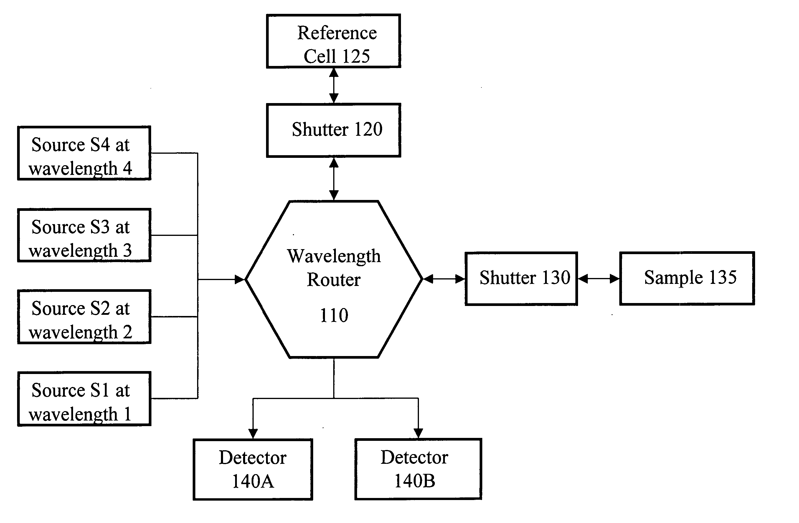
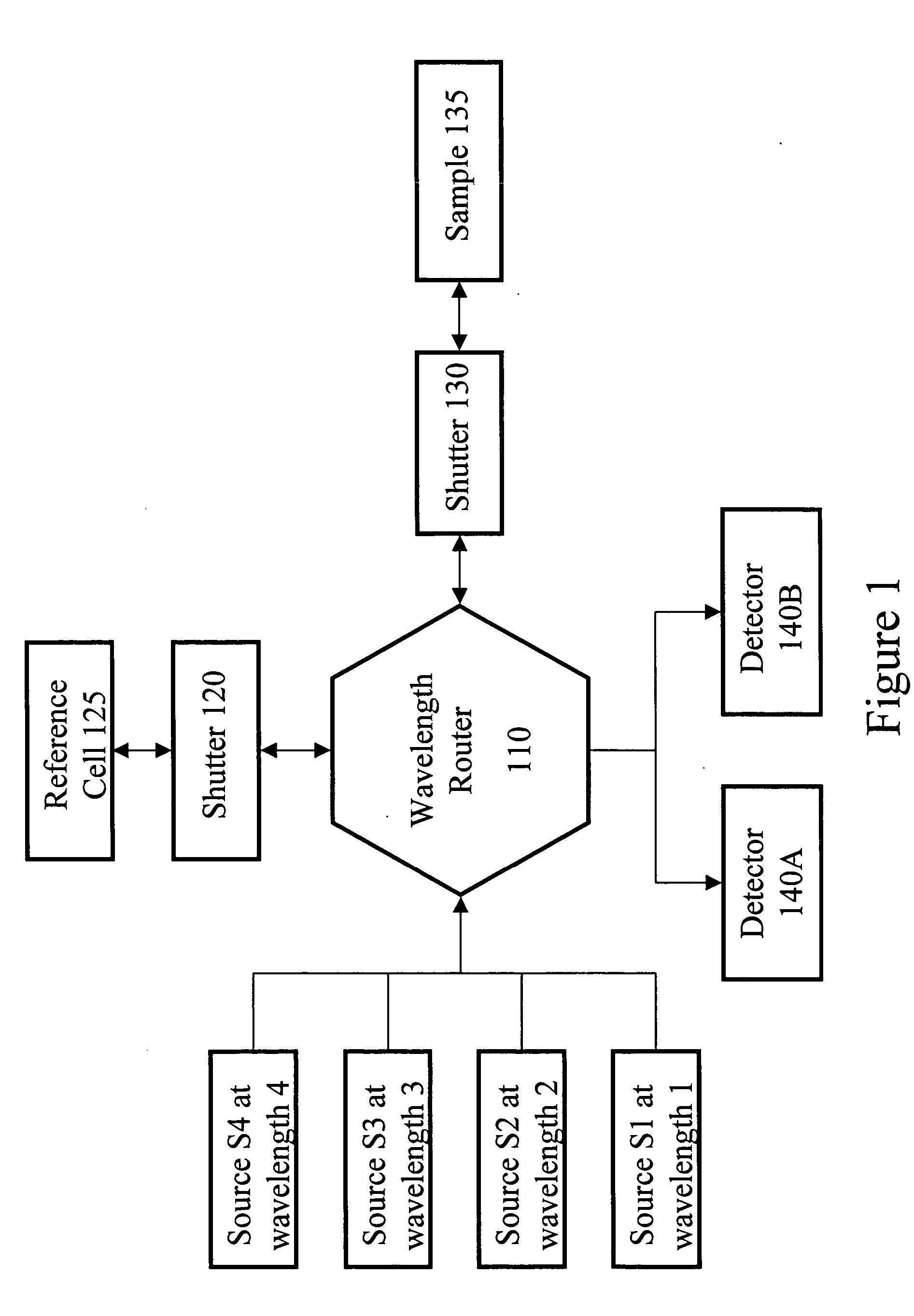
[0027]FIG. 1 is a high-level block diagram of a device according to the invention, primarily showing the optical functionality of the major components within the device. In this particular example, the device includes four sources S1-S4, two detectors 140A-B, a reference cell 125 and shutter 120, a sample 135 and shutter 130, and a wavelength router 110.

[0028] Generally speaking, the device operates as follows. The sources S1-S4 produce light that is routed by the wavelength router 110 to the reference cell 125 and / or sample 135 via the respective shutter 120,130. The shutters 120,130 allow time gating of the illumination. Light scattered from the reference cell 125 and / or sample 135 is routed by the wavelength router 110 to the detectors 140.

[0029] The sources S1-S4 are shown as having a diversity of wavelengths (wavelengths 1-4 in FIG. 1). The wavelength router 110 directs a linear combination of the incident light from the sources S1-S4 via the shutters 120,130 to the sample 13...


PUM

PropertyMeasurementUnit
angleaaaaaaaaaa
spectral widthsaaaaaaaaaa
half widthaaaaaaaaaa

Abstract

Weak signals scattered from analytes at multiple wavelengths can be summed to illuminate either a single detector or a multiplicity of detectors, offering the possibility of concentrating the spectral energy on a smaller total detector area. In addition, a method is disclosed whereby a calibration of the resulting signal for a given analyte can be obtained by means of measuring the quantity of water in the sample volume and by means of measuring the salinity of the fluid in the sample volume.

Description

CROSS-REFERENCE TO RELATED APPLICATION [0001] This application claims priority under 35 U.S.C. § 119(e) to U.S. Provisional Patent Application Ser. No. 60 / 497,072, filed Aug. 22, 2003.BACKGROUND OF THE INVENTION [0002] 1. The Field of the Invention [0003] This invention relates generally to measuring analytes in samples and, more specifically, to measuring analytes based on an electromagnetic spectrum that is characteristic of the analyte, for example as can be used to make non-invasive measurements of analytes in biological organisms. [0004] 2. Background and Relevant Art [0005] Many attempts have been made to create appropriate apparatus for the non-invasive measurement of significant substances within biological organisms. The importance of such measurement capability arises not only from the need to observe biochemical reactions in such organisms without disturbance to the system but also in order to help control chronic diseases such as diabetes, where it is highly desirable to...

Claims


Application Information

Patent Timeline
Patent Type & Authority Applications(United States)
IPC IPC(8): A61B5/00G01J3/30G01J3/42G01J3/427G01J3/44G01NG01N21/27G01N21/31G01N33/487G03H1/00
CPCG01J3/02G01J3/0229G01J3/0232G03H1/0005G01J3/44G01N21/274G01N21/31G01J3/1838G01J3/30G01J3/42G01J3/427
Inventor LIPSON, JAN
Owner REDOX BIOMEDICAL
Why Eureka
Try Eureka