
Hangar bar

a hanger bar and cathode technology, applied in the field of cathode, can solve the problems of relatively poor electrical conductivity of steel, reduce the electrical resistance to current, and reduce the possibility of bi-metallic corrosion of the join

Active Publication Date: 2005-06-16
MOUNT ISA MINES
View PDF6 Cites 20 Cited by
  • Summary
  • Abstract
  • Description
  • Claims
  • Application Information

AI Technical Summary

Benefits of technology

[0013] The use of stainless steel as the support element imparts strength, long term durability and corrosion resistance for the hanger bar. These features are clearly important in obtaining an extended operational life for the hanger bar. However, as is well known in the art, stainless steel is a relatively poor electrical conductor. The introduction of an electrically conductive metal cladding will permit the ready transfer of electrical current along the hanger bar into the blade of the cathode plate.
[0016] In a preferred embodiment, the electrically conductive cladding surrounds the exposed portions of the support element, and extends part way down from the support element along the blade of the cathode. This embodiment reduces the electrical resistance to current passing through the bar onto the blade and in addition reduces the possibility of bi-metallic corrosion of the joint between the electrically conductive metal and the cathode blade which is normally made from stainless steel.
[0017] In addition to the aforementioned advantages arising from use of the hanger bar, the production of the hanger bar itself is much simpler that conventional mechanisms. For instance, it is not necessary to use a portion of the hanger bar as weld material. Nor is it necessary to electroplate the hanger bar. As will be known to persons skilled in the art, in one conventional technique, for production of the cathode plate, after the hanger bar is welded to the cathode blade, the entire assembly is inverted and dipped into an electrolytic bath a sufficient depth to electroplate the hanger bar with a conductive metal. The cost and handling difficulties associated with this mechanism are clear. Affixing a cladding of electrically conductive metal to the support element is much simpler, more cost effective and more accurate than current techniques.

Problems solved by technology

However, as is well known in the art, stainless steel is a relatively poor electrical conductor.

Method used


Image

  • Hangar bar
  • Hangar bar

Examples


Embodiment Construction

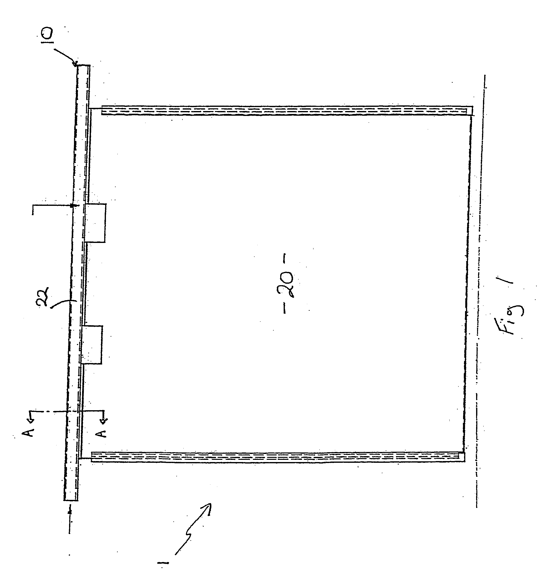
[0024] As shown in FIG. 1, a cathode plate 1 comprises a hanger bar 10 and a cathode blade 20. Windows 15 are cut from the cathode blade 20 to assist in lifting and transportation of the cathode 1.

[0025] As mentioned above, when electro-refining copper according to the ISA PROCESS, the cathode blade 20 is a stainless steel blade. However, it will be appreciated that the blade can be manufactured from any suitable material. Titanium and other metals may be used in electro-refining operations.

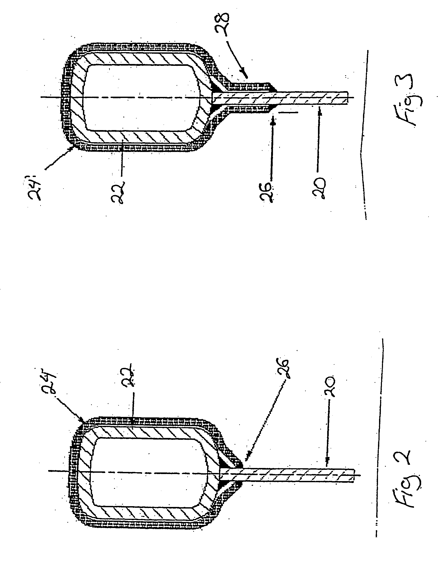
[0026] As shown more clearly in FIG. 2, the hanger bar 10 comprises a support element 22 with a cladding 24 of electrically conductive metal affixed thereto.

[0027] In this embodiment the support element 10 is stainless steel bar. The stainless steel bar 22 is hollow but is preferably sealed at the ends. It is not essential that the stainless steel bar 22 be hollow.

[0028] The cladding of electrically conductive material 24, in this example copper, is affixed around the stainless steel bar 22. ...


PUM

PropertyMeasurementUnit
Lengthaaaaaaaaaa
Electrical conductivityaaaaaaaaaa
Electrical conductoraaaaaaaaaa

Abstract

A hangar bar for a cathode plate and a method of producing a cathode for electrolytic recovery of metal. The hanger bar comprises a support element which is preferably stainless steel and hollow. An electrically conductive metal cladding is affixed the stainless steel bar by any appropriate mechanism, eg interference fit, welding, chemical or mechanical fastening or coextrusion or roll forming. Affixing the cladding to the stainless steel support element has significant advantages over conventional electroplating techniques including that a more precise engineering specification can be applied to the cladding thickness. This is important to maintain vertical alignment of the cathode plate in the electrolytic cell.

Description

TECHNICAL FIELD [0001] The present invention relates to cathodes used in electrolytic recovery of metals. 1. Background Art [0002] Any discussion of the prior art throughout the specification should in no way be considered as an admission that such prior art is widely known or forms part of common general knowledge in the field. [0003] There are various processes and apparatus for electro-refining or electro-winning of metal. One particularly successful process for electro-depositing of copper, for example, is the so called ISA PROCESS. In this process, stainless steel cathode mother plates are immersed in an electrolyte bath with copper anodes. The copper from the anodes dissolve into the electrolyte and are subsequently deposited in a refined form onto the blade of the mother plate. The electrolytically deposited copper is then stripped from the blade by first flexing the cathode plate to cause at least part of the copper deposit to separate from the blade, and then wedge strippin...

Claims


Application Information

Patent Timeline
IPC IPC(8): C25C7/02
CPCC25C7/02Y10T29/49892Y10T29/53204Y10T29/5313
Inventor WEBB, WAYNE KEITH
Owner MOUNT ISA MINES
Learn More