Method for manufacturing a transparent element with invisible electrodes

Active Publication Date: 2005-06-16
THE SWATCH GRP RES & DEVELONMENT LTD
View PDF6 Cites 26 Cited by
  • Summary
  • Abstract
  • Description
  • Claims
  • Application Information

AI Technical Summary

Benefits of technology

[0011] The method enables very good anti-reflective properties to be obtained, but also excellent optical compensation and much better abrasion resistance, given the possible choices of dielectric material for forming the outermost layer.
[0012] In a preferred embodime

Problems solved by technology

First of all, it is expensive because of the number of different films that have to be deposited by CVD or equivalent methods.
It is also difficult to implement, in particular during the electrode structuring step where there is a high risk of the last dielectric film being damaged and thus new problems of interference being created, m

Method used


Image

  • Method for manufacturing a transparent element with invisible electrodes
  • Method for manufacturing a transparent element with invisible electrodes

Examples


Embodiment Construction

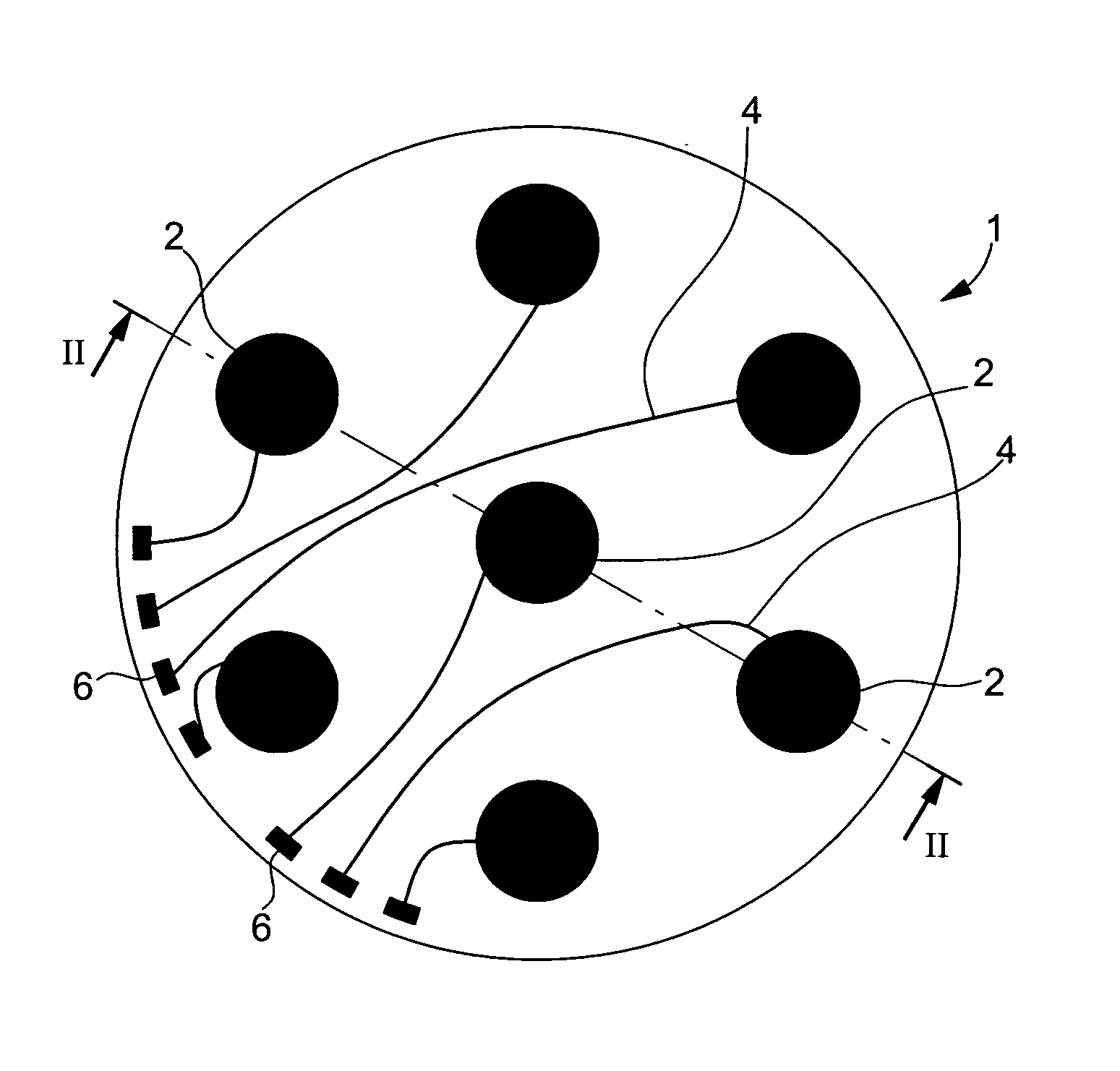
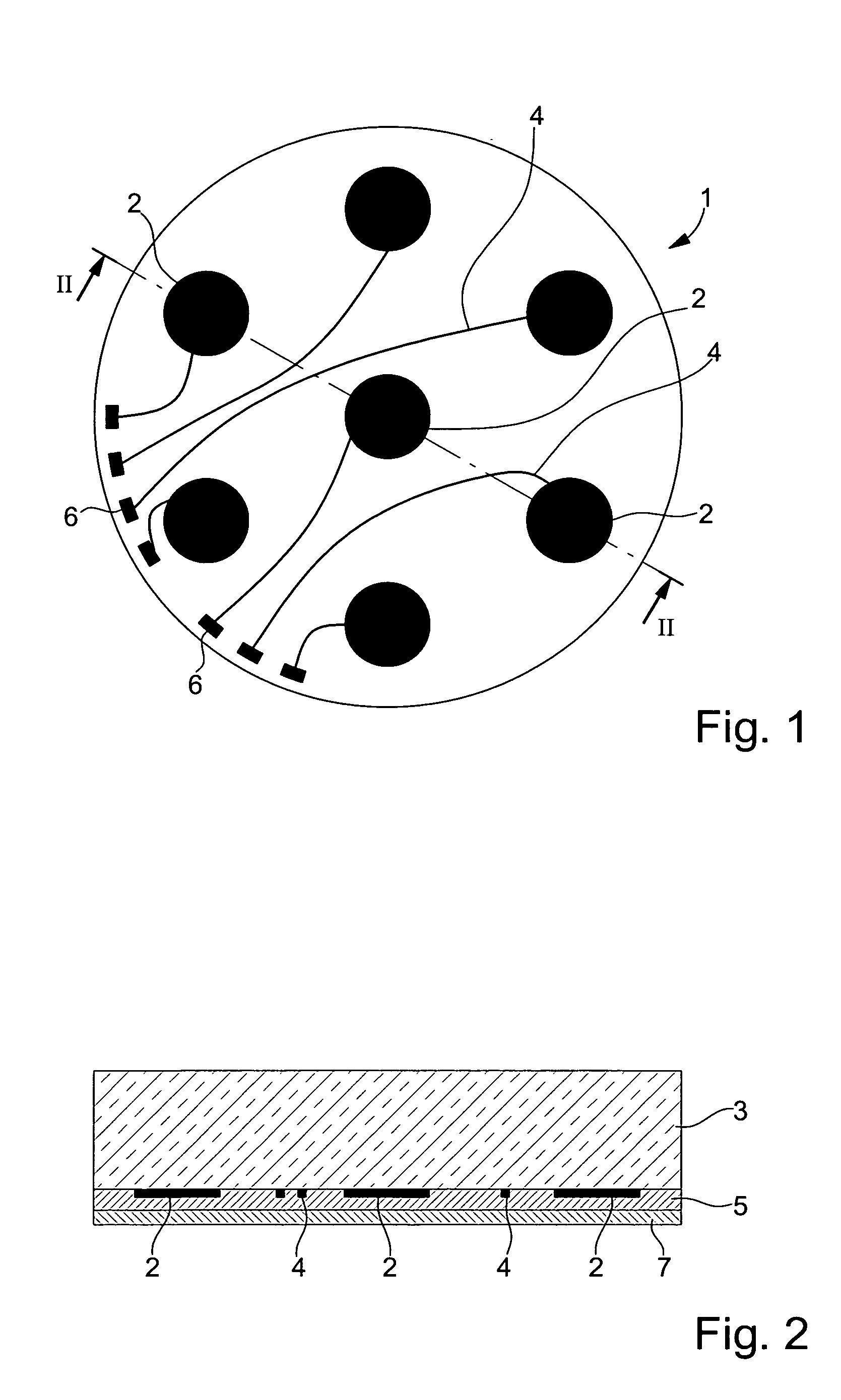
[0016]FIG. 1 shows a bottom view of glass 1 made of sapphire or toughened glass, to be mounted in a wristwatch, said glass 1 being formed by a transparent substrate 3 including a pattern of transparent conductive oxides (TCO) forming the electrodes of capacitive touch type sensors 2 that can be actuated by the contact of a finger on the outer surface of glass 1, said sensors 2 being connected by conductive paths 4 to peripheral contact zones 6, themselves connected to the electronic movement of the wristwatch and / or microprocessors for controlling time or non-time related functions. Although the contrasts have been greatly exaggerated in FIG. 1, all of these conductive elements 2, 4, 6 would be visible through glass 1, in particular in oblique observation, if no treatment had been carried out.

[0017] Referring now to FIG. 2, there is described hereinafter the method according to the invention, which makes sensors 2, conductive paths 4, and less necessarily, contact zones 6, which ca...


PUM

PropertyMeasurementUnit
Temperatureaaaaaaaaaa
Thicknessaaaaaaaaaa
Thicknessaaaaaaaaaa

Abstract

A conductive pattern, made of a transparent conductive oxide, such as ITO including electrodes (2) and conductive paths (4) is formed on one face of a transparent substrate (3) made of sapphire or toughened glass, then coated with a first layer (5) of a transparent dielectric with a low refractive index, such as MgF2 or LiF2, and then a second layer (7) of another transparent dielectric having a higher refractive index than the first, such as Al2O3, Ta2O5 or DLC.

Description

[0001] This application claims priority from European Patent Application No. 03028874.0 filed Dec. 16, 2003, the entire disclosure of which is incorporated herein by reference. FIELD OF THE INVENTION [0002] The present invention concerns a method for manufacturing a transparent element including electrodes whose contours cannot be perceived in the visible light wavelength range owing to a particular arrangement of transparent dielectric materials that also provide an anti-reflective effect. BACKGROUND OF THE INVENTION [0003]“Transparent element” means in a non-limiting manner ocular lens, watch glasses, touch screens with transparent electrodes, for example structured on watch glasses, or even the transparent plates of a liquid crystal display cell or a photovoltaic cell. [0004] An anti-reflective effect is obtained in a known manner by forming, on a transparent substrate (S), a stack including at least one layer of a transparent dielectric material with a high refractive index (H) ...

Claims


Application Information

Patent Timeline
IPC IPC(8): H01B13/00C03C17/34G03F7/00G04B39/00G06F3/033G06F3/044H03K17/96
CPCC03C17/3411C03C17/3417C03C17/3452C03C2217/734C03C2217/94Y10S977/811C03C2218/34G04B39/002G04B39/006G06F3/044H03K17/962C03C2218/33G03F7/00
Inventor GRUPP, JOACHIMPOLI, GIAN-CARLO
Owner THE SWATCH GRP RES & DEVELONMENT LTD
Why Eureka
Try Eureka