Area-efficient compensation circuit and method for voltage mode switching battery charger

a compensation circuit and battery charger technology, applied in electric power, transportation and packaging, electric vehicles, etc., can solve the problems of die size and cost penalties, variability in the gain of transconductance amplifiers with process and temperature variation, etc., to improve the performance of compensation amplifiers, reduce the required die area, and improve the effect of compensation amplifier performan

a compensation circuit and battery charger technology, applied in electric power, transportation and packaging, electric vehicles, etc., can solve the problems of die size and cost penalties, variability in the gain of transconductance amplifiers with process and temperature variation, etc., to improve the performance of compensation amplifiers, reduce the required die area, and improve the effect of compensation amplifier performan

US20050134220A1Inactive Publication Date: 2005-06-23BROHLIN PAUL L +2

Image

  • Area-efficient compensation circuit and method for voltage mode switching battery charger
  • Area-efficient compensation circuit and method for voltage mode switching battery charger
  • Area-efficient compensation circuit and method for voltage mode switching battery charger

Examples


Embodiment Construction

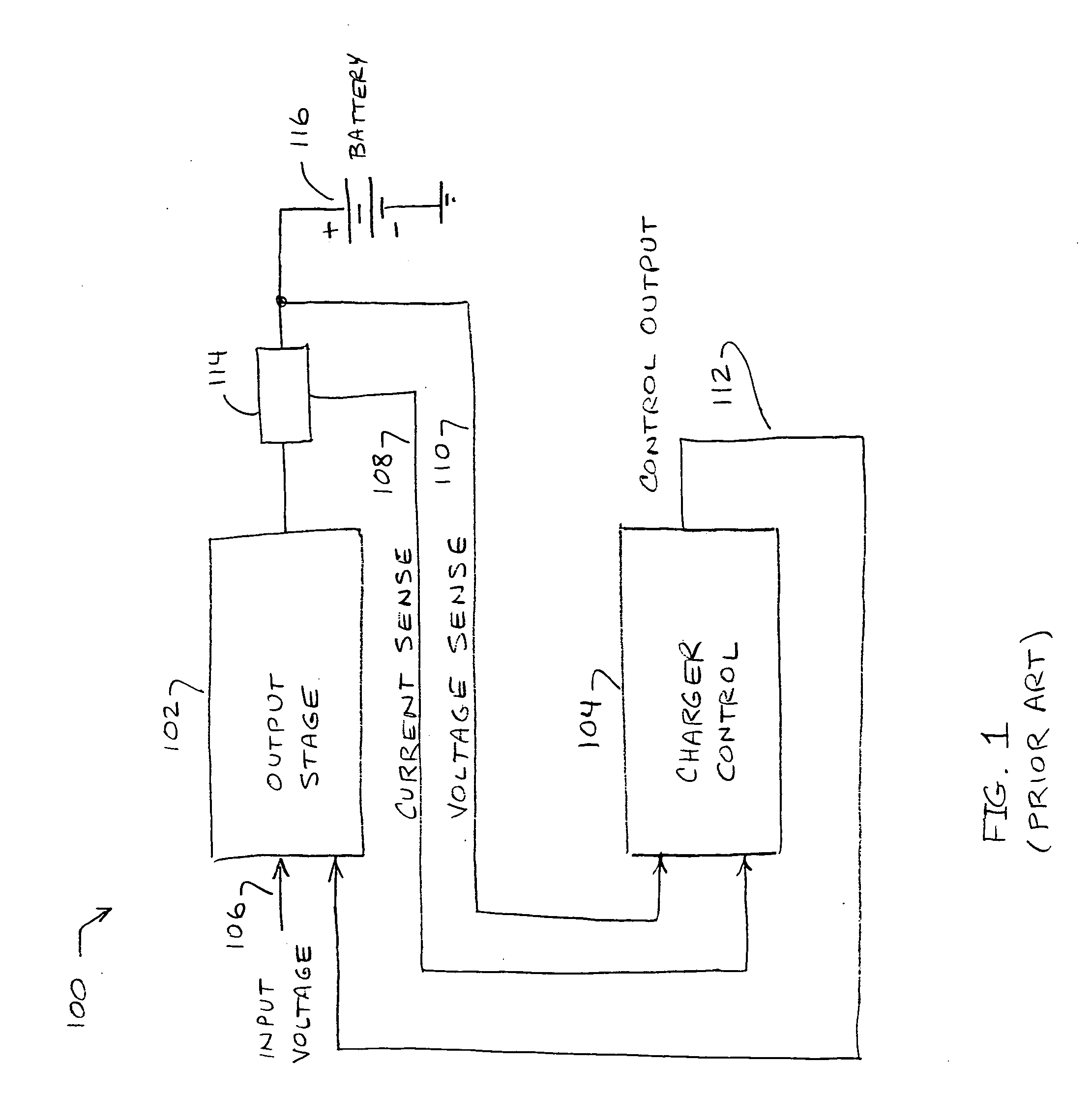
[0021] As shown in FIG. 1, a typical battery charger 100 has an input voltage applied to the input 106 of an output stage 102. Output stage 102 is a voltage-controlled current source (VCCS) which serves to regulate the flow of current from input 106 to a battery 116 which is to be charged. Battery charging current is sensed by a sensor 114 at the output of output stage 102. Sensor 104 outputs a voltage representing the charging current to a first input 108 of a charger control circuit 104. Voltage on the battery 116 is also sensed, and is applied to a second input 110 of charger control circuit 104. Charger control circuit 104 is adapted and configured in response to the inputs 108, 110, to determine whether a constant current or constant voltage should be applied to the battery 116 being charged. In response to this determination, a control signal is applied by way of feedback to a control input 112 of the VCCS 102, to set the current into or voltage applied to battery 116 (as appr...


PUM


Abstract

A feedback-controlled battery charger circuit (500) provides, alternatively, constant current and constant voltage to a battery (328) being charged. Current and voltage at the charger output (326) are sensed in sensing elements (308) and compared to preset reference values from reference generators for current (330) and voltage (332), thus generating error signals for both current and voltage. These error signals are amplified in separate amplifiers (530, 534); then, depending on battery voltage, one of the amplified error signals is automatically selected by a signal selector (540). The selected error signal is applied to a single compensation amplifier (554) with reactive feedback loop (552, 556); the output of the compensation amplifier with feedback (504) then controls the output current or voltage of the output stage (306). This output stage is a voltage controlled current source. The output of this voltage controlled current source is connected through an output filter (318) and sensing elements (308) to the battery (328) being charged.

Description

CROSS-REFERENCE TO RELATED APPLICATIONS [0001] This application claims priority under 35 U.S.C. 119 of U.S. Patent Application Ser. No. 60 / 524,193, filed Nov. 21, 2003, entitled โ€œArea-Efficient Compensation Method for Voltage-Mode Switching Battery Chargers,โ€ the entirety of which is incorporated herein by reference.BACKGROUND OF THE INVENTION [0002] 1. Field if the Invention [0003] This invention relates to battery chargers in general, and, in particular, to a compensation method for a dual voltage mode, constant current constant voltage (CC-CV), DC-DC step-down switching battery charger using negative feedback for regulation of charging current and voltage. [0004] 2. Description of the Related Art [0005] Modern battery chargers are designed to accurately regulate both charging current and charging voltage. One class of chargers is referred to as constant-current, constant-voltage (CC-CV) chargers. [0006] Lithium (Li+) battery chargers follow a predetermined charging profile to ens...

Claims


Application Information

Patent Timeline
23 Jun 2005
Publication
US20050134220A1
IPC
H02J7/00
CPC
H02J7/0072; H02J7/0052; H02J7/00711; H02J7/00714; H02J7/007182; H02J7/00
Inventors
BROHLIN, PAUL L.; MARTINEZ, ROBERT