Hologram making method

a hologram and making method technology, applied in the field of one-step type hologram making method, can solve the problems of substantial reduction, achieve the effects of improving uniformity and efficiency, uniform illumination, and reducing the angle of divergen

Inactive Publication Date: 2005-06-23
HAMAMATSU PHOTONICS KK
View PDF6 Cites 2 Cited by
  • Summary
  • Abstract
  • Description
  • Claims
  • Application Information

AI Technical Summary

Benefits of technology

[0028] When the imaging optical system includes two lenses, between which a spatial light modulating device is disposed, the spatial light modulating device image is projected onto the recording surface while a magnification thereof is changed. In particular, since the magnification optical system and the diffuser improve the uniformity and efficiency in the luminous flux incident on the spatial light modulating device while reducing the angle of divergence, the uniformity of illuminance of the finally projected spatial light modulating device image on the recording surface can be maintained even when the spatial light modulating device is uniformly illuminated while maximally utilizing the diameter of the upstream-side lens on which the diverged light is incident and when the magnification is changed.
[0029] Preferably, letting λ be the wavelength of the luminous flux emitted from the diffuser, DS be the diameter of the lens on the diffuser side in the two lenses, LS be the distance between this lens and the spatial light modulating device, θ be the angle formed between the optical axis of this lens and a segment connecting a radial end part of the lens and an end part of the spatial light modulating device, and P be the interval between pixels in the spatial light modulating device, DS and LS are set such that θ is sin−1 (λ / P) or greater. In this case, substantially all of the luminous fluxes outputted from the diffuser and the upstream-side lens can be made incident on the spatial light modulating device, so as to improve the in-plane uniformity of the luminous fluxes incident on the spatial light modulating device, thereby reducing the noise included in the reconstructed image.

Problems solved by technology

Therefore, even when noise exists in the reconstructed image of the display surface itself or in the reconstructed image of the projected image of the display surface, the noise itself is fixed at the observing position and thus is unremarkable as noise, thereby being reduced substantially.

Method used


Image

  • Hologram making method
  • Hologram making method
  • Hologram making method

Examples


first embodiment

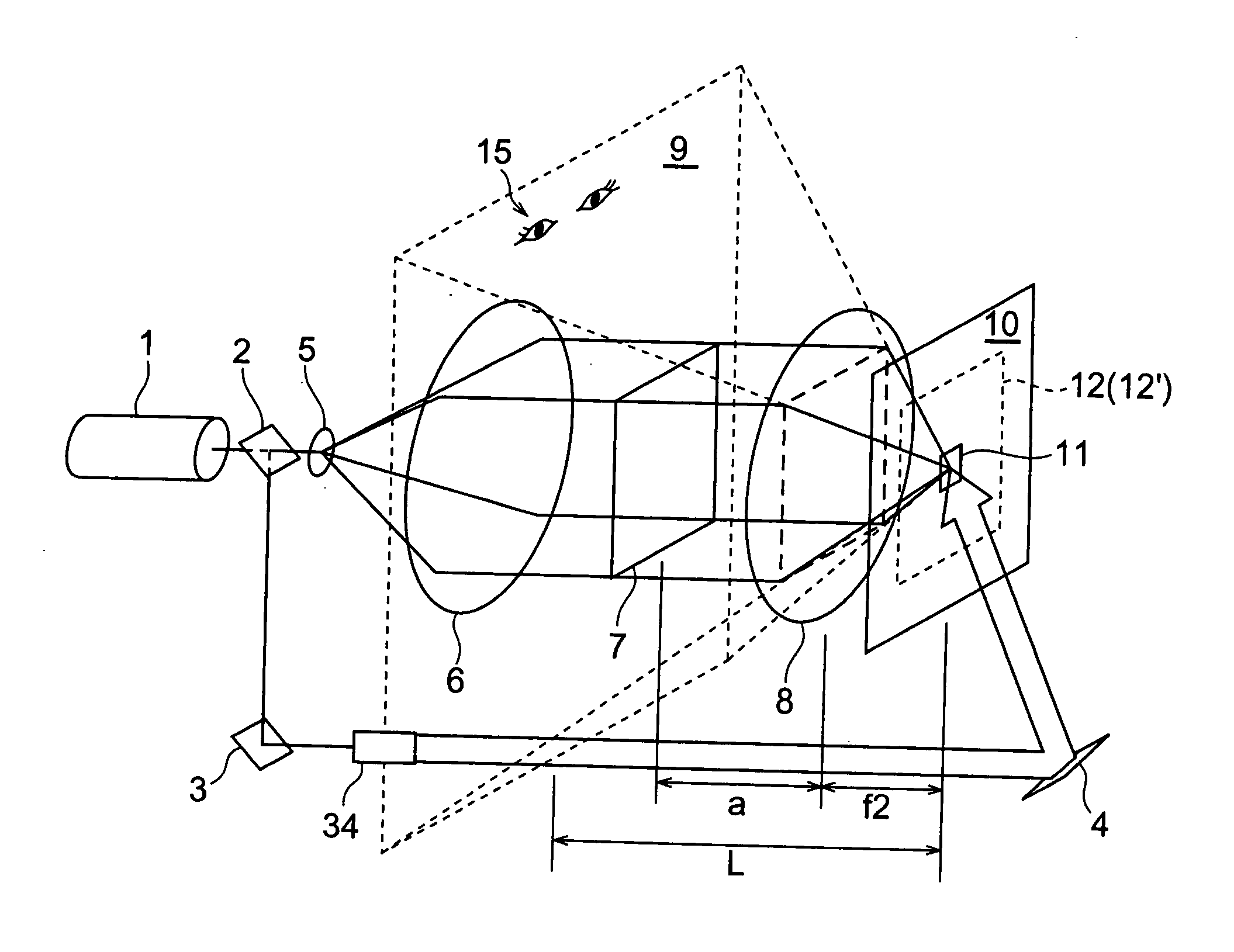
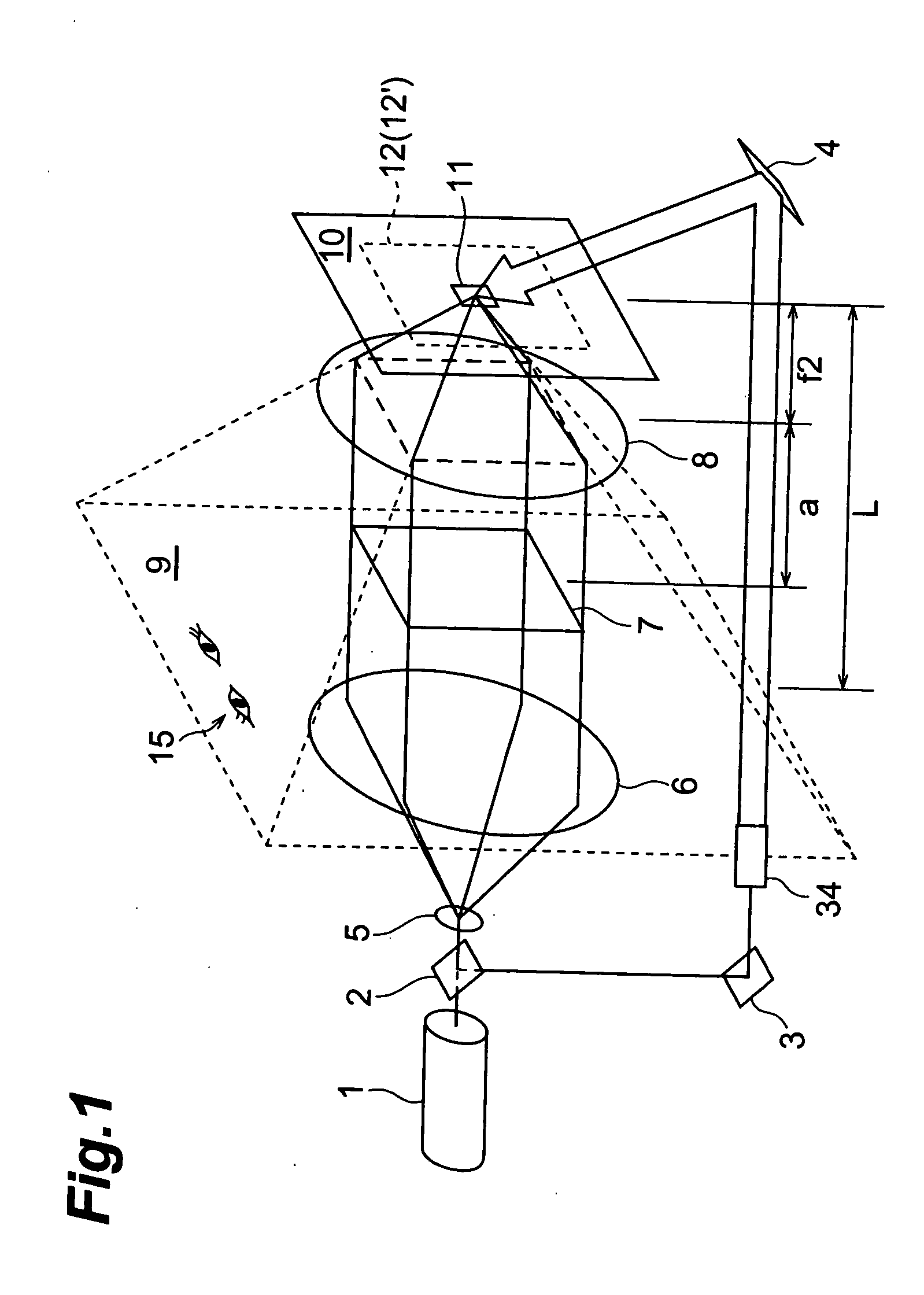
[0039]FIG. 1 is an explanatory view of a hologram making apparatus equipped with an optical system in the case where an image of a spatial light modulating device is turned into a virtual image, whereas a viewpoint is placed at the virtual image position. This will be explained in detail in the following.

[0040] This apparatus comprises a laser light source (coherent light source; semiconductor laser) 1 emitting a laser beam having a single wavelength, and a half mirror 2 for splitting the laser beam emitted from the laser light source 1. The laser beams split by the half mirror 2 pass through (i) an object light irradiation optical system and (ii) a reference light irradiation optical system, thereby irradiating the surface (front face) and rear face of a photosensitive material 12, respectively.

[0041] (i) Object Light Irradiation Optical System

[0042] The object light irradiation optical system comprises a beam expander composed of lenses 5 and 6 arranged such that the light pass...

second embodiment

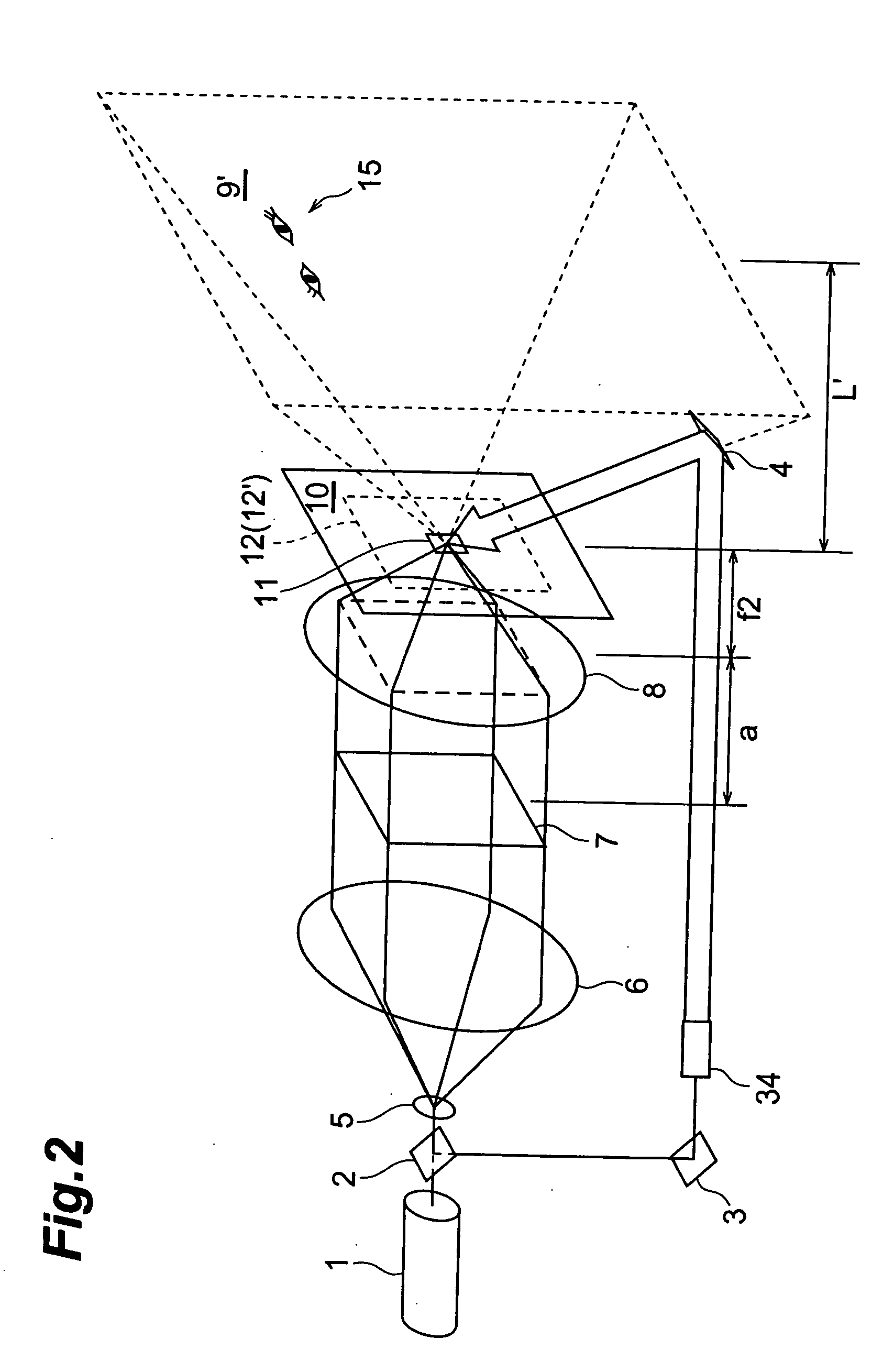
[0062]FIG. 2 is an explanatory view of a hologram making apparatus equipped with an optical system for turning an image of a spatial light modulating device into a real image while placing the viewpoint at the real image position. This apparatus is the same as that of the first embodiment except that the spatial light modulating device 7 is disposed on the light source side from the object-side focal position of the lens 8. In the same process as that mentioned above, a hologram 12′ is made from a photosensitive material 12 in this example.

[0063] In the case where a>f2 explained in this example, the light image emitted from the spatial light modulating device 7 at the time of making the hologram 12′ inherently forms an image at a position (referred to as real image position and indicated by the distance L′ from the hologram 12′ (photosensitive material 12)) farther distanced from the lens 8 than the image-side focal position of the lens by passing through the lens 8. Namely, the ob...

third embodiment

[0069]FIG. 3 is an explanatory view of a hologram making apparatus equipped with an optical system in the case where an image of a spatial light modulating device 7 is projected onto a diffuser screen′, and thus projected image is turned into a virtual image, whereas a viewpoint is placed at the virtual image position. In the apparatus in accordance with this embodiment, the diffuser screen 7′ is disposed at the position of the spatial light modulating device 7 in accordance with the first embodiment. This apparatus is configured such that the object light emitted from the spatial light modulating device 7 illuminated by a beam expander 5, 6 is projected onto the diffuser screen 7′ by way of an imaging lens PJ, in which the diffuser screen 7′ acts like the spatial light modulating device 7 described in the first embodiment. Namely, in this example, the spatial light modulating device 7 in the first embodiment is read as the diffuser screen 7′.

[0070] Since the spatial light modulati...


PUM

PropertyMeasurementUnit
sizeaaaaaaaaaa
sizeaaaaaaaaaa
sizeaaaaaaaaaa

Abstract

The distance between a spatial light modulating device 7 and a lens 8 is set such that a real or virtual image position 9, 9′ (L, L′) of object light formed by the lens 8 is an observing position of a hologram 12′. Since a reconstructed image is fixed at the observing position L, L′, noise existing in the reconstructed image of the spatial light modulating device 7′ if any is fixed at the observing position and thus is unremarkable as noise, whereby the noise is substantially lowered.

Description

TECHNICAL FIELD [0001] The present invention relates to a one-step type hologram making method. BACKGROUND ART CONVENTIONAL EXAMPLE 1 [0002] Japanese Patent Application Laid-Open No. HEI 3-249686 discloses an example of making a one-step type Lippmann hologram having longitudinal and lateral parallaxes. [0003]FIG. 8 is a diagram showing the two-dimensional hologram making apparatus disclosed in the above-mentioned publication. In this hologram making apparatus, laser light outputted from a laser light source 103 is split into two beams by a beam splitter 104. One of thus split laser beams is caused to expand its luminous flux diameter by a lens system and is made incident on a spatial light modulating device F′ such as a transmission type liquid crystal display. After being subjected to amplitude modulation by individual pixels of the spatial light modulating device F′ displaying images from respective viewpoints prepared by a computer, this laser beam is converged by a lens onto a ...

Claims


Application Information

Patent Timeline
Patent Type & Authority Applications(United States)
IPC IPC(8): G02F1/13G03H1/04G03H1/26
CPCG03H1/0248G03H1/0486G03H1/26G03H2223/14G03H2001/0428G03H2001/2685G03H2001/0415G03H1/00
Inventor TAKEMORI, TAMIKIKON, KENJI
Owner HAMAMATSU PHOTONICS KK
Why Eureka
Try Eureka