
Process for purifying phenol-containing bisphenol A

Active Publication Date: 2005-06-23
MITSUBISHI CHEM CORP
View PDF4 Cites 0 Cited by
  • Summary
  • Abstract
  • Description
  • Claims
  • Application Information

AI Technical Summary

Benefits of technology

[0010] part of the liquid phase obtained in the second step being circulated back to the first step and fed into a flash evaporator along with the crude molten bisphenol A to effect purification of bisphenol A. It is thereby possible to harvest high-quality bisphenol A in a stabilized way from a crude melt of bisphenol A containing phenol.
[0012] In the present invention, the crude molten bisphenol A containing phenol, which is to be purified, is in the first step supplied to a flash evaporator for undergoing flash evaporation to be thereby separated into a gaseous phase comprising phenol and a liquid phase comprising bisphenol A and residual (unevaporated) phenol. As the crude molten bisphenol A containing phenol, there can be used an adduct of bisphenol A with phenol (this adduct usually contains 30 to 60% by weight of phenol and other light ends), but it is preferable to use the melt from which part of phenol has already been evaporated away, as this serves for lessening the amount of phenol to be evaporated in the first step. Usually, a bisphenol A / phenol adduct from which part of phenol has been removed to concentrate bisphenol A to not less than 65% by weight, preferably not less than 70% by weight, is supplied to the first step. It is the most preferable to use an adduct in which bisphenol A has been concentrated to 73 to 77% by weight.
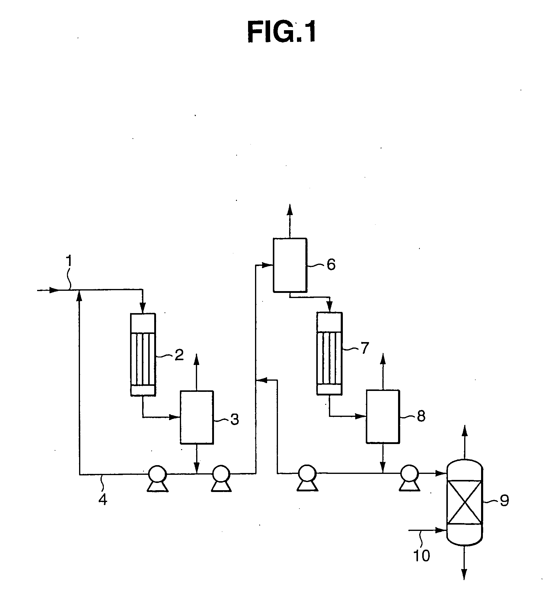
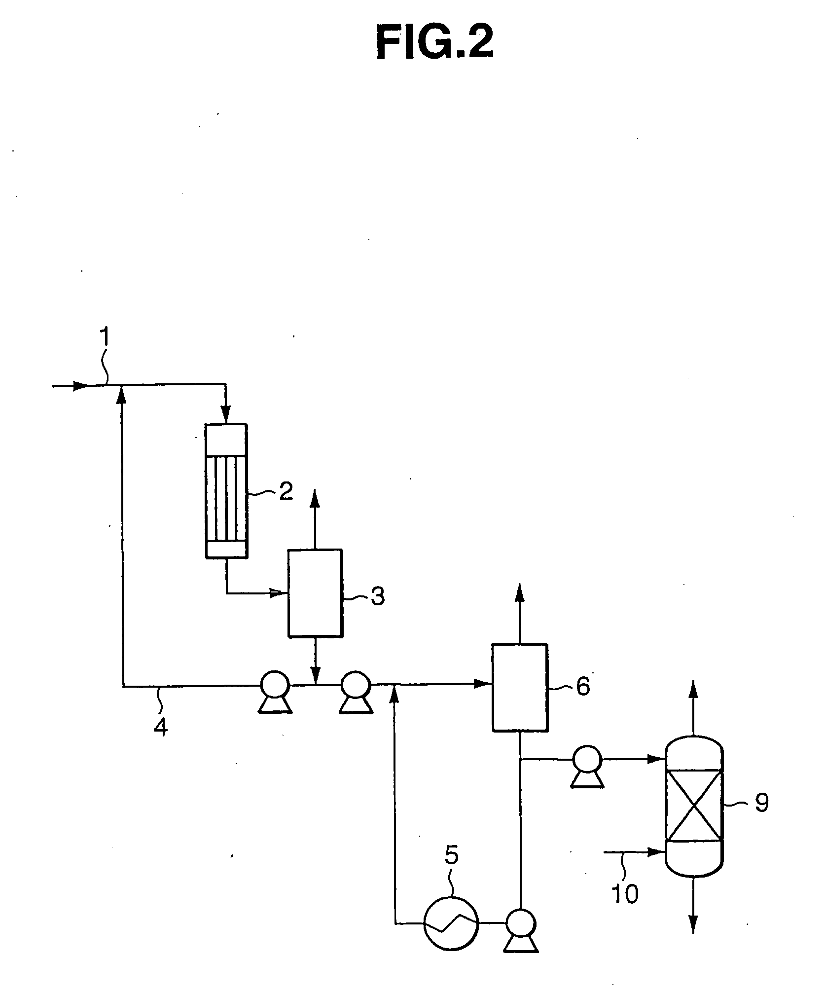
[0015] Flash evaporation in the first step is naturally conducted under a pressure lower than the operating pressure of the said thin film evaporator, usually under a pressure of not higher than 100 Torr, preferably not higher than 60 Torr, especially 10 to 60 Torr. A large amount of phenol is contained in the phenol-containing crude molten bisphenol A yielded from the thin film evaporator. Therefore, if this melt is supplied as is to the flash evaporator, temperature drops acutely with evaporation of phenol, which may cause generation of the crystals of bisphenol A in the flash evaporator. In the present invention, in order to avoid such generation of crystals of bisphenol A, the said phenol-containing crude molten bisphenol A is mixed with a concentrated solution of bisphenol A prepared in the second step to raise the concentration of bisphenol A and then supplied to the flash evaporator. This can lessen the drop of temperature in the flash evaporator. Since the melting point of bisphenol A is 156 to 157° C., the mixing rate of the concentrated solution of bisphenol A supplied from the second step in the phenol-containing crude molten bisphenol A is preferably decided so that the temperature in the evaporator will not become lower than the above-shown melting point of bisphenol A even if a desired amount of phenol has been evaporated by flash evaporation.
[0016] The liquid phase produced by flash evaporation in the first step is then heated by a thin film evaporator in the second step and separated into a gaseous phase comprising phenol and a liquid phase comprising bisphenol A and residual phenol. As the thin film evaporator, it is preferable to use a natural falling-thin film type as in the case where the light ends are evaporated from the melt of the bisphenol A / phenol adduct. The pressure in this evaporator is maintained equal to or higher than the pressure in the flash evaporator in the first step. The heating temperature is usually 170° C. to 200° C., preferably 180° C. to 190° C. It is possible to let vapor and liquid effuse separately from each other from the thin film evaporator in the second step, but preferably they are discharged out together and supplied to a gas / liquid separator to effect sufficient separation of gas and liquid. Part of the liquid phase formed by this gas / liquid separation is circulated to the first step in the same way as described above and mixed with the phenol-containing crude molten bisphenol A supplied to the first step. This liquid circulation has the effect of flash-evaporating, along with phenol, the thermal decomposition products formed by heating in the second step, in addition to its above-mentioned function to lessen the drop of temperature in flash evaporation in the first step.
[0017] The concentrated liquid of bisphenol A obtained in the second step is preferably further purified by steam stripping. Steam stripping is an operation in which the concentrated liquid of bisphenol A is supplied to a packed column from its top while steam is supplied from the bottom of the column to effect countercurrent contact between the falling liquid and the rising steam to remove phenol entrained by the steam effused from the column top. This operation is preferably conducted under the same pressure as or a lower pressure than used in the second step, usually with the column top pressure of 10 to 60 Torr. The temperature is preferably selected such that purified bisphenol A yielded from the column bottom will have a temperature of 160° C. to 220° C., preferably 170° C. to 190° C. A high temperature may induce thermal decomposition of bisphenol A. The ratio of steam to the concentrated liquid of bisphenol A supplied to the packed column is usually 2 to 8% (by weight). Steam stripping makes it possible to obtain bisphenol A with very high purity and excellent hue.

Problems solved by technology

However, in order to remove phenol sufficiently without much raising the degree of vacuum, it needs to elevate the operating temperature, which involves the possibility of causing thermal decomposition of bisphenol A.
However, flash evaporation under a high degree of vacuum may cause separating of bisphenol A or the bisphenol A / phenol adduct as a solid because of excessive drop of temperature.
Also, when flash evaporation is carried out at a high temperature, bisphenol A may be decomposed when heated to produce isopropenylphenol or such, resulting in a deteriorated hue of obtained bisphenol A.
However, in case where the circulating liquid is heated for the purpose of evaporating a large amount of residual phenol in the flasher system, it is necessary to heat the liquid to an excess degree, so that the above proposal can not be said the best method.
As viewed above, many proposals have been made on the method of harvesting bisphenol A from phenol-containing bisphenol A by evaporating phenol, but none of them is enough satisfactory.

Method used


Image

  • Process for purifying phenol-containing bisphenol A
  • Process for purifying phenol-containing bisphenol A

Examples


example 1

[0019] A melt of an adduct of bisphenol A with phenol (56% by weight of bisphenol A, 44% by weight of phenol and 0% by weight of isopropenylphenol) was purified according to the process shown by the flow sheet of FIG. 1.

[0020] 23.4 parts by weight / hr of a melt (150° C.) of a bisphenol A / phenol adduct supplied via conduit 1 and 15 parts by weight / hr of a liquid circulated from a gas / liquid separator 3 via conduit 4 were mixed and led into a natural falling-thin film evaporator 2 maintained under an internal pressure of 300 Torr. Evaporator 2 was heated with steam so that the effluent liquid would have a temperature of 180° C. The liquid and gas effusing from evaporator 2 were guided into a gas / liquid separator 3 and thereby separated into gas and liquid under 300 Torr. The concentration of bisphenol A in the effluent liquid from evaporator 2 was 73.6% by weight, and the concentration of bisphenol A in the liquid extracted from gas / liquid separator 3 was 74.5% by weight, with the con...

example 2

[0023] Purification of bisphenol A was conducted under the same operating conditions as in Example 1 except that the pressure of flash evaporator 6 was raised from 15 Torr to 60 Torr. The results are shown in Table 1.

example 3

[0024] Purification of bisphenol A was conducted under the same operating conditions as in Example 1 except that the pressure of flash evaporator was raised from 15 Torr to 60 Torr while the liquid temperature at the outlet of evaporator 7 was elevated from 180° C. to 200° C. The results are shown in Table 1.


PUM

PropertyMeasurementUnit
Temperatureaaaaaaaaaa

Abstract

The process of the present invention comprises a first step in which crude molten bisphenol A containing phenol is supplied to a flash evaporator and separated into a gaseous phase comprising phenol and a liquid phase comprising bisphenol A and residual phenol, and a second step in which the liquid phase obtained in the first step is heated by a thin film evaporator and separated into a gaseous phase comprising phenol and a liquid phase comprising concentrated bisphenol A and residual phenol, part of the liquid phase obtained in the second step being circulated to the first step and supplied to the flash evaporator along with crude molten bisphenol A. It is possible with this process to obtain high-quality bisphenol A stably from phenol-containing bisphenol A.

Description

TECHNICAL FIELD [0001] The present invention relates to a process for purifying bisphenol A by removing phenol from phenol-containing bisphenol A (viz. 2,2-bis(4-hydroxyphenyl)propane). BACKGROUND ART [0002] Bisphenol A is an important chemical product as a base material of polycarbonate resins, epoxy resins and such, and is produced industrially on a large scale through the reaction of phenol and acetone. For isolating bisphenol A from the reaction mixture, the reaction mixture is first concentrated and then cooled to let bisphenol A crystallize as an adduct with phenol, and the adduct is subjected to a suitable solid / liquid separating means such as centrifuge to separate the crystals from the mother liquor. [0003] This bisphenol A / phenol adduct is then melted and distilled to separate it into bisphenol A and phenol. Since bisphenol A tends to be thermally decomposed and transformed into isopropenylphenol or such when exposed to a high temperature, the distillation of the bipshenol...

Claims


Application Information

Patent Timeline
IPC IPC(8): C07C37/68C07C37/74C07C39/16
CPCC07C37/685C07C37/74C07C39/16C07C37/68
Inventor KIMURA, HIROAKI
Owner MITSUBISHI CHEM CORP
Learn More