Inorganic matrix-fabric system and method

a technology of organic matrix and material, applied in the direction of earthwork drilling and mining, building components, textiles and paper, etc., can solve the problems of structural failure of concrete structures, collapse, cracking, and partial loss of concrete structures, and achieve high degree of resistance to alkali attack, and high degree of chemical resistance

Inactive Publication Date: 2005-06-30
ALDEA CORINA MARIA +1
View PDF85 Cites 25 Cited by
  • Summary
  • Abstract
  • Description
  • Claims
  • Application Information

AI Technical Summary

Benefits of technology

[0011] The preferred alkali-resistant fibrous layer is comprised of AR-glass having a sizing applied thereon, and a resinous coating applied over the sizing, the inorganic matrix being adherent to the resinous coating and the resinous coating being adherent to the sizing. Unlike other types of glass fibers, such as E-glass, AR-glass has a high degree ...

Problems solved by technology

The steel reinforcement provides a great deal of added structural strength (e.g., compression, tensile, flexural and/or shear-resistance) to the support, but there have been numerous incidents of structural failure of these supports when subjected to asymmetric loads and horizontal displacement generated during earthquakes or explosions.
Concrete structures, while adequate in compression, are subject to cracking, collapse, and partial loss due to stresses associated with earthquakes, explosions, land subsidence and overloading.
Structural failure of such structures can have devastating consequences.
However, there are ...

Method used


Image

  • Inorganic matrix-fabric system and method
  • Inorganic matrix-fabric system and method
  • Inorganic matrix-fabric system and method

Examples


specific examples

[0079] This invention and its advantages are further described with reference to the following specific examples. The examples are merely intended to be illustrative and not to be construed as limiting the scope of the invention. In the following examples the method as described above was employed and tested on masonry wall and triplet samples. Results were obtained which indicate significantly improved seismic strengthening for the overall support system.

example 1

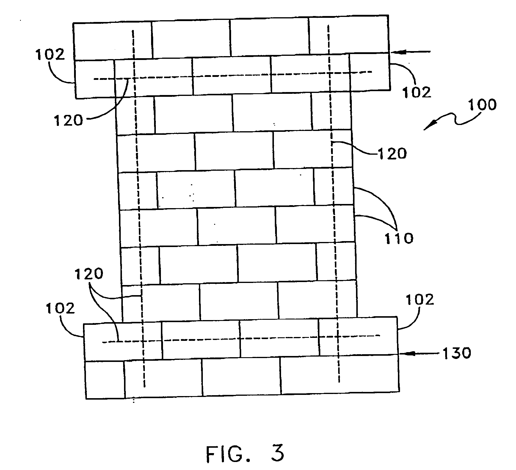
[0080] Referring to FIG. 3, a lightly reinforced sample CMU block wall 100 (wall 1) was constructed from standard 8×8×16 in. CMUs 110. The CMUs were constructed of a type N mortar, consisting of 1 part sand, 3 parts Type I Portland cement, 1 part hydrated lime, and water in sufficient quantity to make the mortar mix workable by the technician. The wall was ten courses high with the top two and bottom two courses 16 in. wider than the central six courses forming an “I” shape. All of the blocks in the top two and bottom two courses were fully grouted to get better load transfer from a load frame (see FIG. 4) during testing and increase the probability of wall failure not occurring within the wide top and bottom sections of the wall. A #4 steel reinforcing bar 120 was placed in the cells surrounding the central pier. All blocks containing steel reinforcing bars were fully grouted. Three-eighth inch face shell mortar bedding was used on the CMU blocks with the cross webs of units adjace...

example 2

[0089] A second wall sample 200 (wall 2) having a reinforcement system applied was tested using the same testing method as described above with respect to wall sample 1. Wall 2 was made in accordance with the materials and procedure described in Example 1 and the reinforcement system applied to wall 2 was made with the materials described in Example 1. The only difference between Examples 1 and 2 is with respect to the method of reinforcement application. In applying the reinforcement system of wall 2, the first glass fibrous layer was oriented so that the weft direction of the fabric having two rovings was at a 45° angle to the bottom of the wall running from the top left corner (US) to the bottom right corner (LN). The second glass fibrous layer was oriented so that the weft direction of the fibrous layer was aligned perpendicular to the bottom of the sample wall 200.

[0090] Referring to FIG. 8, the reinforcement of wall 2 began to show cracking at 0.3 inch horizontal displacement...


PUM

PropertyMeasurementUnit
Angleaaaaaaaaaa
Fractionaaaaaaaaaa
Fractionaaaaaaaaaa

Abstract

A method of reinforcing a structural support, includes applying a reinforcement system comprising an AR-glass fibrous layer embedded in an inorganic matrix to the structural support. The AR-glass fibrous layer has a sizing applied thereon, and a resinous coating applied is applied over the sizing. The inorganic matrix is adherent to the resinous coating and the resinous coating is adherent to the sizing.

Description

[0001] This application is a division of U.S. patent application Ser. No. 10 / 209,471, filed Jul. 30, 2002, the entire disclosure of which is incorporated by reference herein.FIELD OF THE INVENTION [0002] This invention relates to structural supports, and more particularly to a method and reinforcement system for strengthening of such structural supports. BACKGROUND OF THE INVENTION [0003] Walls, columns and other structures constructed of materials such as concrete or cement paste, brick or masonry units, and the like are widely used as support structures. Tunnels, building structural supports, bridge supports, freeway overpass supports and parking structure supports are just a few of the many uses for these cementitious structural supports. These supports may exist in a wide variety of shapes with circular, square and rectangular cross-sections being the most common. However, numerous other cross-sectional shapes have been used, including regular polygonal shapes and irregular cros...

Claims


Application Information

Patent Timeline
IPC IPC(8): B32B5/02E21D11/04C03B37/10D02G3/00E04B2/00E04CE04C5/00E04C5/04E04C5/07E04G23/00E04G23/02
CPCE04G23/0218B32B17/04C04B28/02C03C25/1095Y10T156/10Y10T29/49618C03C25/103C04B14/42C04B20/023C04B32/02E04G2023/0251Y10T428/24994Y10T428/249924Y10T428/249932Y10T428/249929Y10T428/249946Y10T428/249928Y10T428/249948
Inventor ALDEA, CORINA-MARIAROBERTS, DAVID GERAINT
Owner ALDEA CORINA MARIA
Why Eureka
Try Eureka