Optical recording material and optical recording medium

Inactive Publication Date: 2005-06-30
TKD CORP
View PDF6 Cites 45 Cited by
  • Summary
  • Abstract
  • Description
  • Claims
  • Application Information

AI Technical Summary

Benefits of technology

[0034] In the recording layer of the optical recording medium of the present invention, it is preferred that the cation represented by the above general formula (2) (hereafter, ion (2)) is present more than the aforesaid chelate compound in terms of moles from the viewpoint of enhancing the balance of properties of the medium.
[0035] The optical recording material of the present invention

Problems solved by technology

The salt-forming dye disclosed in JP No. 2000-190641 and JP No. 2000-190642 did not necessarily

Method used


Image

  • Optical recording material and optical recording medium
  • Optical recording material and optical recording medium
  • Optical recording material and optical recording medium

Examples


example 1

[0107] A polycarbonate resin substrate was prepared of diameter 120 mm and thickness 0.6 mm having a pre-groove (depth 180 nm, width 0.30 μm, groove pitch 0.74 μm) on one side. A recording layer coating solution was also prepared by adding a salt-forming dye 1 represented by the following formula (73) to 2,2,3,3-tetrafluoropropanol so that its content was 1.0 mass %.

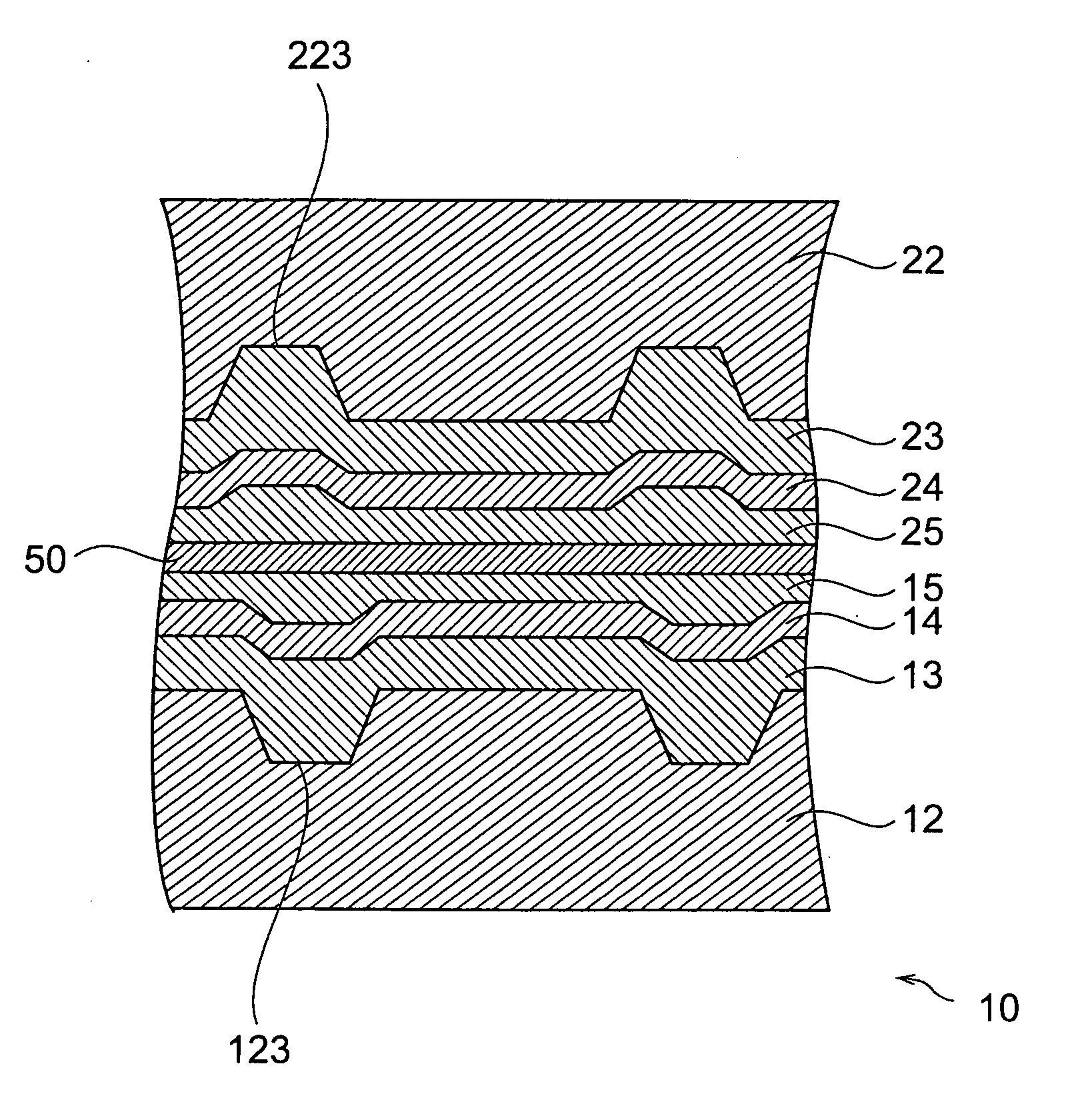
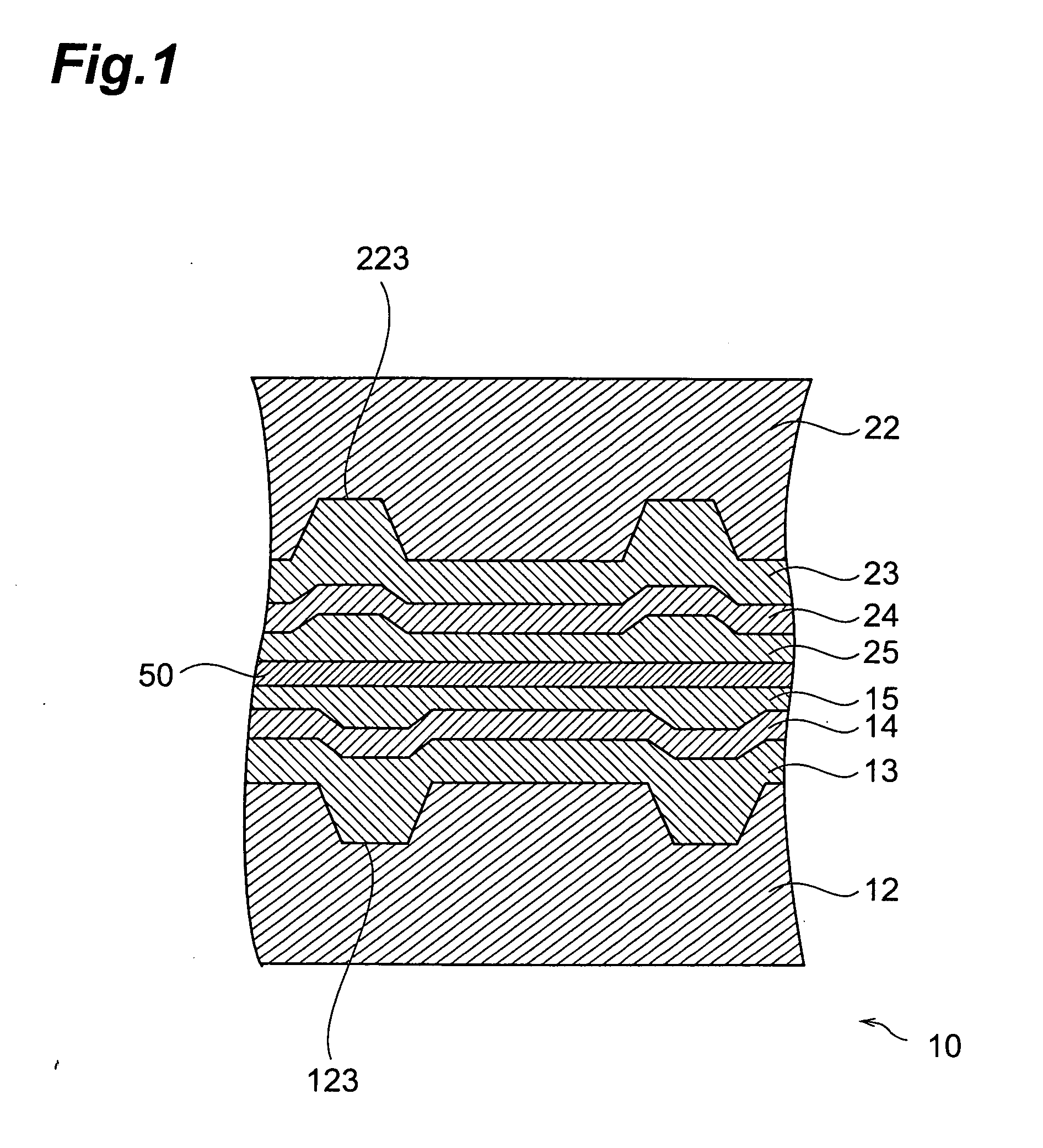
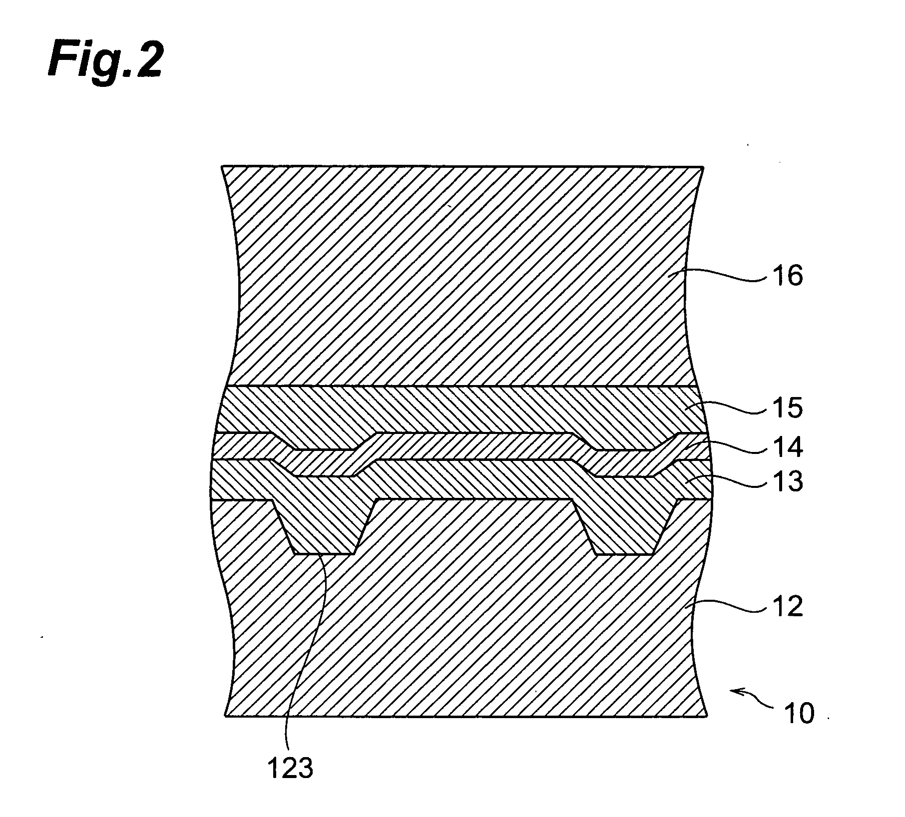
[0108] The obtained coating solution was coated on the surface of the aforesaid polycarbonate resin substrate having the pre-groove formed thereupon, and dried to form a recording layer (thickness 100 nm). Next, an Ag reflecting layer (thickness 85 nm) was formed by sputtering on this recording layer, and a transparent protective layer (thickness 5 μm) comprising an ultraviolet curing acrylic resin was formed on the Ag reflecting layer so as to obtain a laminated structure. Two of these laminated structures were manufactured, and stuck together with their protective layers facing each other using adhesive so as to obta...

example 2

[0109] An optical recording disk was manufactured in an identical manner to that of Example 1, except that the salt-forming dye 2 represented by the following formula (74) was used instead of the salt-forming dye 1 of Example 1.

examples 3-13

, Comparative Example 1-3

[0110] In Examples 3-13 and Comparative Example 1-3, an optical disc was manufactured in an identical manner to that of Example 1, except that the dye compositions 3-13 represented shown in Table 1 were respectively used instead of the salt-forming dye 1. In Table 1, the figures in brackets refer to symbols for chemical structural formulae given hereabove and hereafter.

TABLE 1SaltCyanineChemicalCompositionChemicalCompositionformula No.(mass %)formula No.(mass %)Example 373406160Example 473506150Example 574406560Example 674406660Example 774406760Example 874406860Example 973306170Example 1073606140Example 1173706130Example 1273407760Example 1373407860Comp. Ex. 175707630Comp. Ex. 275100 ——Comp. Ex. 375407660

[0111]

[0112] [Evaluation of Recording / Reproduction Properties]

[0113] Next, a signal was recorded on the optical recording discs of Example 1-13 and Comparative Example 1-3 at a linear speed of 3.5 m / sec or 28.0 m / sec using a laser light of wavelength 655 n...


PUM


Abstract

An optical recording material used in an optical recording medium which can record information by light irradiation, this optical recording material containing a dye compound obtained by salt formation between a chelate compound formed by coordination between one metal and one or two compounds represented by the following general formula (1):
where A and B are groups of atoms which may be identical or different, and which respectively form aromatic rings, and X1 and X2 are respectively functional groups having one or more active hydrogen atoms which may contain a substituent group,
and a cation represented by the following general formula (2):
where C is a group of atoms forming a benzene ring or naphthalene ring which may have a substituent group, R1 and R2 are respectively five-membered rings or six-membered rings which may have a substituent group, Y1 is a substituent group, Q3 is a nitrogen-containing heterocyclic ring which may have a condensed ring, p and q are respectively integers from 1 to 4, and n is an integer from 0 to 3.

Description

BACKGROUND OF THE INVENTION [0001] 1. Field of the Invention [0002] This invention relates to an optical recording material used in an optical recording medium which records information by being irradiated with light, and to an optical recording medium. [0003] 2. Related Art [0004] At present, an optical recording medium generally records information by irradiating a recording layer with a laser, which produces a shape change, magnetic sector change or a phase change in the recording layer. This optical recording medium may for example be a tracking type optical recording medium comprising a recording layer containing an organic dye, such as for example an azo dye (e.g., Japanese Unexamined Patent Application (JP) No. 08-108623, and JP No. 08-156408, which is widely used in CD-R (tracking type compact disks) or DVD±R (tracking type digital video discs). [0005] In recent years, there is a demand for even higher density recording media, and to respond to this demand, there is an incre...

Claims


Application Information

Patent Timeline
IPC IPC(8): G11B7/244B41M5/26G11B7/247G11B7/249G11B7/257
CPCG11B7/24038G11B7/2467G11B7/2472G11B7/2495G11B7/2531G11B2007/24612G11B7/2534G11B7/2536G11B7/256G11B7/2575G11B7/259G11B7/2533
Inventor SHINKAI, MASAHIROMONDEN, ATSUSHITANABE, JUNJITSUKAMOTO, SHUJIHORAI, TAKASHI
Owner TKD CORP
Why Eureka
Try Eureka