Method for manufacturing a light guide plate mold and a light guide plate

a technology of light guide plate and mold, which is applied in the field of manufacturing light guide plate molds and light guide plate, can solve the problems of saving time and money, and achieve the effect of not being overly time-consuming

Inactive Publication Date: 2005-06-30
HON HAI PRECISION IND CO LTD
View PDF2 Cites 15 Cited by
  • Summary
  • Abstract
  • Description
  • Claims
  • Application Information

AI Technical Summary

Benefits of technology

[0019] An object of the present invention is to provide a method for manufacturing a light guide plate which is relatively simple and not unduly time-consuming, said method including a method for manufacturing a mold.

Problems solved by technology

This saves much time and money.

Method used


Image

  • Method for manufacturing a light guide plate mold and a light guide plate
  • Method for manufacturing a light guide plate mold and a light guide plate
  • Method for manufacturing a light guide plate mold and a light guide plate

Examples


Embodiment Construction

[0032] Reference now will be made to the drawings to describe the present invention in detail.

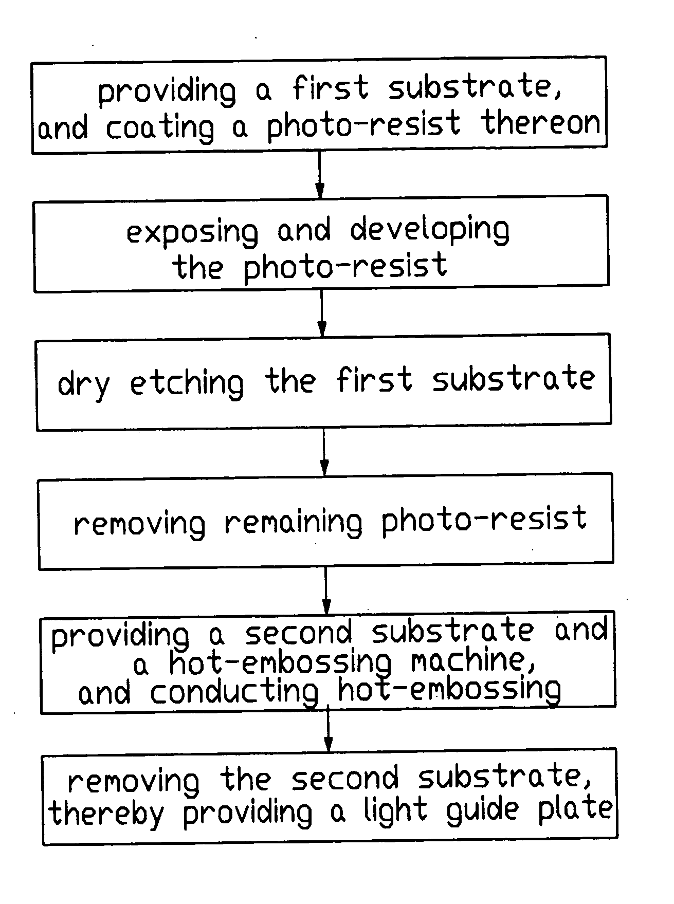
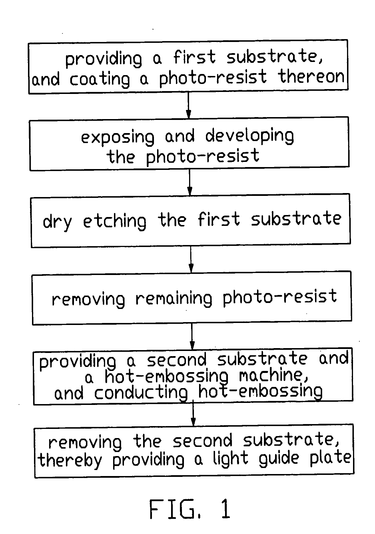
[0033]FIG. 1 is a flow chart for manufacturing a light guide plate. The process includes the steps of: [0034] 1) providing a first substrate, and coating a photo-resist thereon; [0035] 2) exposing the photo-resist using a photo mask having a micro-dot pattern, and developing the photo-resist; [0036] 3) anisotropically dry etching the first substrate so that the pattern of micro-dots of the photo mask is transferred thereto; [0037] 4) removing remaining photo-resist from the first substrate to thereby provide a mold; [0038] 5) providing a second substrate and a hot-embossing machine, and conducting hot-embossing of the second substrate using the mold; and [0039] 6) removing the second substrate from the hot-embossing machine, thereby providing the light guide plate.

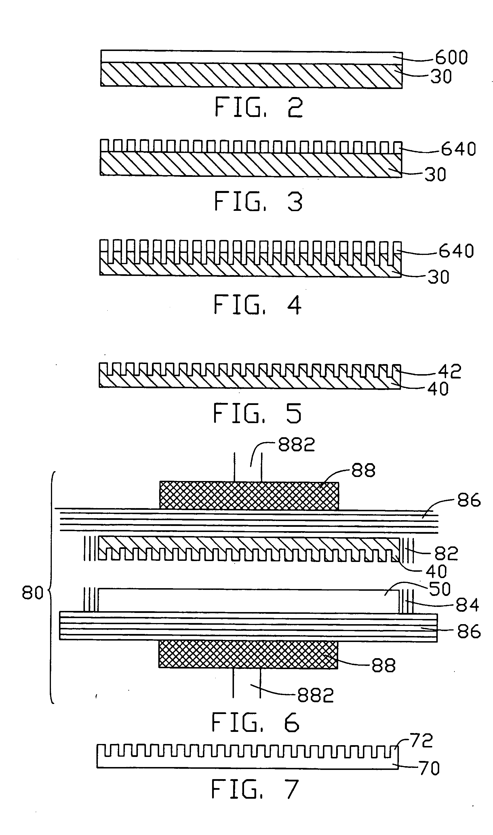
[0040] FIGS. 2 to 7 are schematic, cross-sectional views illustrating stages in the above-described process. FIG. 2 shows the ...


PUM

PropertyMeasurementUnit
diameteraaaaaaaaaa
diameteraaaaaaaaaa
distanceaaaaaaaaaa

Abstract

A method for manufacturing a light guide plate (70) includes: providing a first substrate (30); coating a photo-resist (600) on the first substrate; exposing the photo-resist using a photo mask; developing the photo-resist; anisotropically dry etching the first substrate; removing remaining photo-resist (640), thereby providing a mold (40); providing a second substrate (50) and a hot-embossing machine (80), and conducting hot-embossing of the second substrate using the mold and the hot-embossing machine, thereby providing the light guide plate. By using the above-described dry etching and hot-embossing methods, a pattern of the photo mask is precisely transferred to the first substrate and the light guide plate. A diameter of the each of micro-dots formed on the light guide plate is as little as 10 nanometers. Thus a uniformity of luminance and color provided by the entire light guide plate is improved.

Description

BACKGROUND OF THE INVENTION [0001] 1. Field of the invention [0002] The present invention relates to manufacturing of light guide plates, and particularly to a method for manufacturing a light guide plate using a duly manufactured mold. [0003] 2. Description of the Prior Art [0004] Liquid crystal displays (LCDs) are now in wide spread use in various applications; for example, in desktop computers, portable computers, LCD televisions, portable telephones, etc. An LCD can not itself emit light. A light source system such as back light system is needed for emission of light. A light guide plate is an important part of a back light system, because it controls uniform directionality of emitted light. [0005]FIGS. 8A to 8K represent a conventional process for manufacturing a light guide plate, as disclosed in U.S. Pat. No. 6,522,373 issued on Feb. 18, 2003. The process includes the steps of: [0006] a) applying a primer on a silicon substrate 10 covered with a silicon oxide (SiO2) film 11 t...

Claims


Application Information

Patent Timeline
Patent Type & Authority Applications(United States)
IPC IPC(8): F21V8/00
CPCB82Y20/00G02B6/0065G02B6/0036
Inventor CHEN, GA-LANE
Owner HON HAI PRECISION IND CO LTD
Why Eureka
Try Eureka