Electrically conductive adhesive sheet, method of manufacturing the same, and electric power conversion equipment

a technology of electrical conductive adhesive and adhesive sheet, which is applied in the direction of transportation and packaging, propulsion parts, and multi-division prime-mover propulsion mounting, etc., can solve the problems of thermal fatigue generation in electrical power conversion equipment, particularly large thermal fatigue, etc., and achieves long life extension of equipment, improved contact reliability, and convenient use

Inactive Publication Date: 2005-07-07
HITACHI LTD
View PDF0 Cites 11 Cited by
  • Summary
  • Abstract
  • Description
  • Claims
  • Application Information

AI Technical Summary

Benefits of technology

[0022] In accordance with the present invention, the stress generated by difference in thermal expansion can be moderated as described above, and contact reliability can be improved more than ever. Accordingly, in accordance with the present invention, the

Problems solved by technology

Furthermore, thermal fatigue is generated in the electric power conversion equipment in accordance with heat generation accompanied with operation of the semiconductor element or installation environm

Method used


Image

  • Electrically conductive adhesive sheet, method of manufacturing the same, and electric power conversion equipment
  • Electrically conductive adhesive sheet, method of manufacturing the same, and electric power conversion equipment
  • Electrically conductive adhesive sheet, method of manufacturing the same, and electric power conversion equipment

Examples


embodiment 1

[0048] The embodiment 1 of the present invention is explained hereinafter referring to FIG. 1 to FIG. 6.

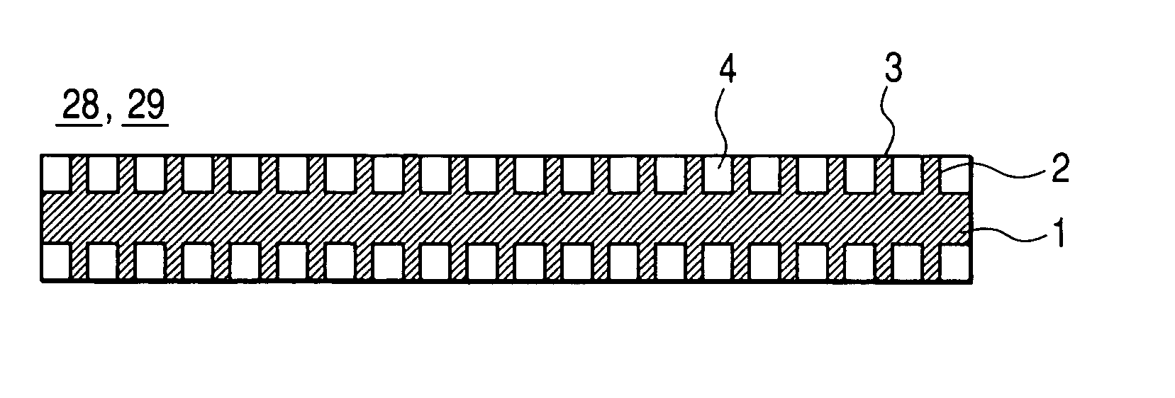
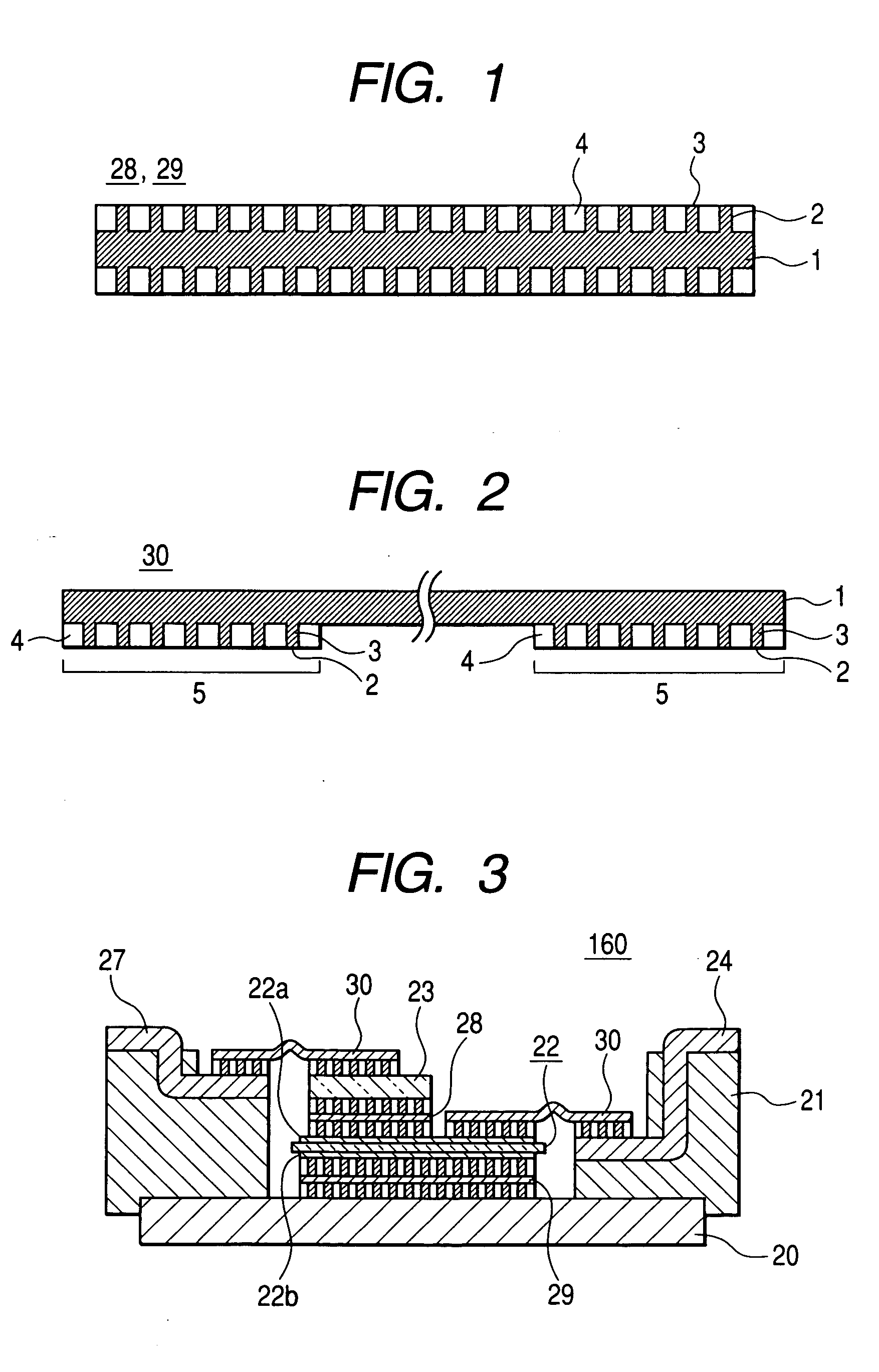
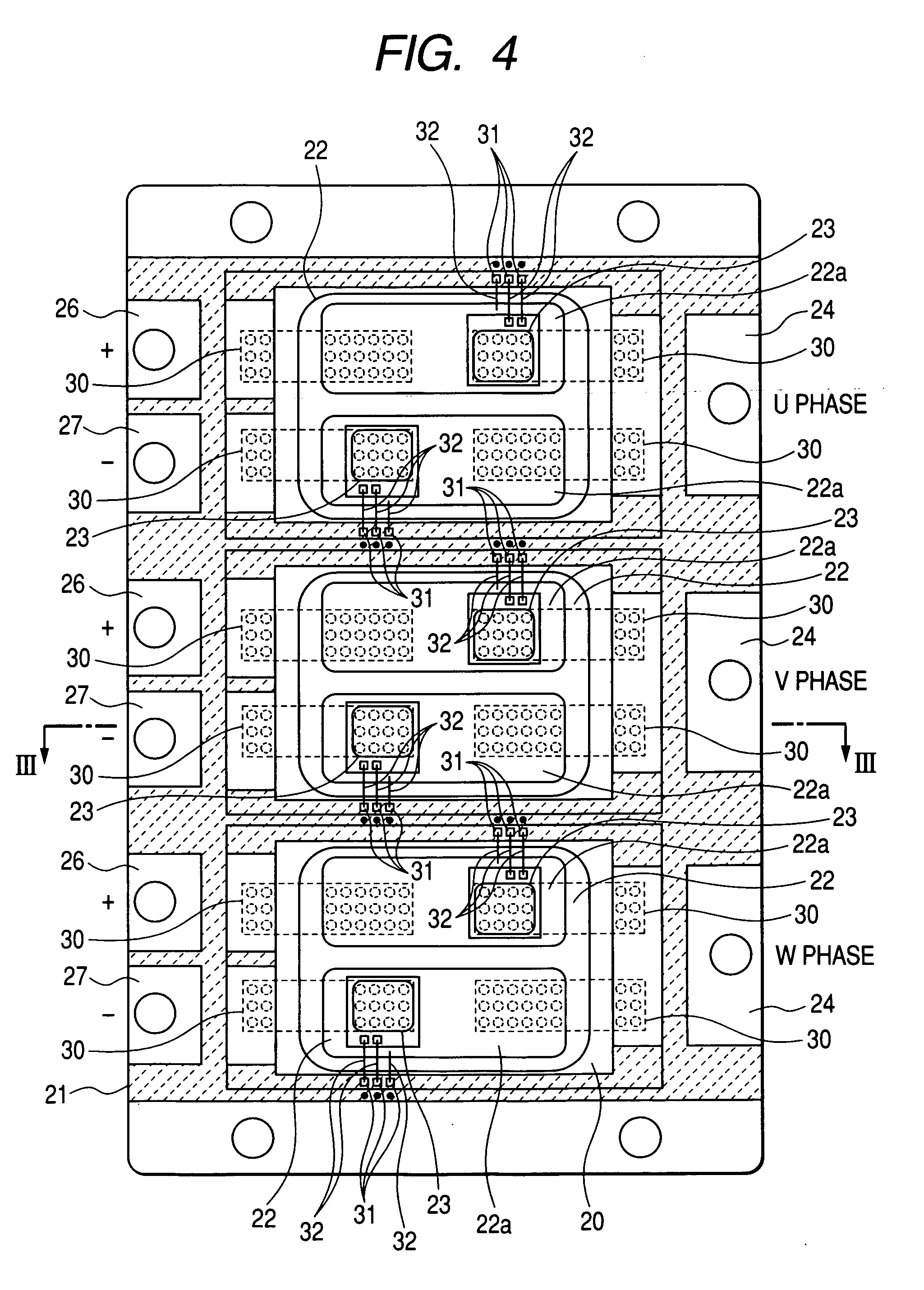
[0049] The electrically conductive adhesive sheet of the present embodiment showing in FIG. 1 and FIG. 2 are applied to the electric power conversion equipment showing in FIG. 3 to FIG. 5 as a bonding member. The electric power conversion equipment showing in FIG. 3 to FIG. 5 is mounted on a vehicle showing in FIG. 6. The electrically conductive adhesive sheet relating to the present embodiment is particularly useful as a bonding member of electric conversion equipment for vehicle which has severe thermal cycles, but it can be applied to also electric power conversion equipment for industries or home appliance, and other semiconductor devices as a bonding member which can replace solder and wire.

[0050] First, an outline of the power train composition of the vehicle showing in FIG. 6 is explained hereinafter. The vehicle showing in FIG. 6 is one of hybrid electric vehicles which ...

embodiment 2

[0107] A method of manufacturing the electrically conductive adhesive sheet, which is the embodiment 2 of the present invention, is explained hereinafter. The composition of the electrically conductive adhesive sheet of the present embodiment is as same as the composition of the electrically conductive adhesive sheet of the embodiment 1. Furthermore, the present embodiment is explained on the manufacturing method of the electrically conductive adhesive sheet having the same structure as the embodiment 1 for example, in which the protrusion layer 2 is provided on both sides of the substrate 1, but the method is applicable to the structure, in which the protrusion layer 2 is provided only on one side of the substrate 1.

[0108] First Manufacturing Step:

[0109] Both sides of iron-nickel alloy foil (made by Hitachi Metal Co.: YEF42) containing Nickel 42% by weight of 35 μm thick are electroplated with copper. Accordingly, the substrate 1 made of iron-nickel alloy foil, both sides of whic...

embodiment 3

[0119] A method of manufacturing the electrically conductive adhesive sheet, which is the embodiment 3 of the present invention, is explained hereinafter. The composition of the electrically conductive adhesive sheet of the present embodiment is as same as the composition of the electrically conductive adhesive sheet of the embodiment 1. Furthermore, the present embodiment is explained on the manufacturing method of the electrically conductive adhesive sheet having the same structure as the embodiment 1 for example, in which the protrusion layer 2 is provided on both sides of the substrate 1, but the method is applicable to the structure, in which the protrusion layer is provided only on one side of the substrate 1.

[0120] First Manufacturing Step:

[0121] Both sides of iron-nickel alloy foil (made by Hitachi Metal Co.: YEF42) containing Nickel 42% by weight of 35 / I m thick are electroplated with copper. Accordingly, the substrate 1 made of iron-nickel alloy foil, both sides of which...


PUM

PropertyMeasurementUnit
Fractionaaaaaaaaaa
Percent by massaaaaaaaaaa
Electrical conductivityaaaaaaaaaa

Abstract

In order to solve the issue mentioned above, the present invention is featured in electrically conductive adhesive sheet: wherein the substrate 1 which composes electrically, thermally, or electrically and thermally conducting paths in a direction along the plane of the sheet is formed of metallic foil having a coefficient of thermal expansion between the coefficient of thermal expansion of one of at least two bonded members and the coefficient of thermal expansion of another one of the bonded members.
In accordance with the present invention adopting the composition mentioned above, a stress applied to the protrusion layer 2, which composes electrically, thermally, or both electrically and thermally conducting paths between the substrate 1 and the bonded members by difference in thermal expansion, can be moderated.

Description

CLAIM OF PRIORITY [0001] The present application claims priority from Japanese application serial no. 2004-000734, filed on Jan. 6, 2004, the content of which is hereby incorporated by reference into this application. BACKGROUND OF THE INVENTION [0002] The present invention relates to electrically conductive adhesive sheet, a method of manufacturing the same, and an electric power conversion equipment. [0003] As for a bonding member of semiconductor element with electrically conductive member, for instance, sheet members disclosed in the following Japanese Laid-open Patent Publication JP-A-6-291226(1994) and Japanese Laid-open Patent Publication JP-2003-273294(2003) are known. The sheet member disclosed in Japanese Laid-open Patent Publication JP-A-6-291226(1994) is manufactured by cladding a metallic foil with resin wherein metallic particles are dispersed. The sheet member disclosed in Japanese Laid-open Patent Publication JP-2003-273294(2003) is manufactured by providing plural m...

Claims


Application Information

Patent Timeline
IPC IPC(8): B60W10/08H01L23/36H01L23/367H01L23/48H01L23/488H01L25/07H05K3/32
CPCB60K6/26B60K6/48H01L2924/1305Y10T428/12556H01L2924/13055H01L2924/13091H01L2924/19107B60W10/08H01L23/367H01L23/48H01L23/488H01L25/072H05K3/321H05K2201/0373H05K2201/1028Y02T10/6221H01L2224/49175H01L2924/00H01L2224/05554Y02T10/62H01L2224/0603
Inventor SUWA, TOKIHITOSHIGETA, SATORUSHIRAKAWA, SHINJIOCHIAI, YOSHITAKA
Owner HITACHI LTD
Why Eureka
Try Eureka