
Analyzing cartridge and liquid feed control device

Inactive Publication Date: 2005-07-07
ASAHI KASEI KK
View PDF20 Cites 155 Cited by
  • Summary
  • Abstract
  • Description
  • Claims
  • Application Information

AI Technical Summary

Benefits of technology

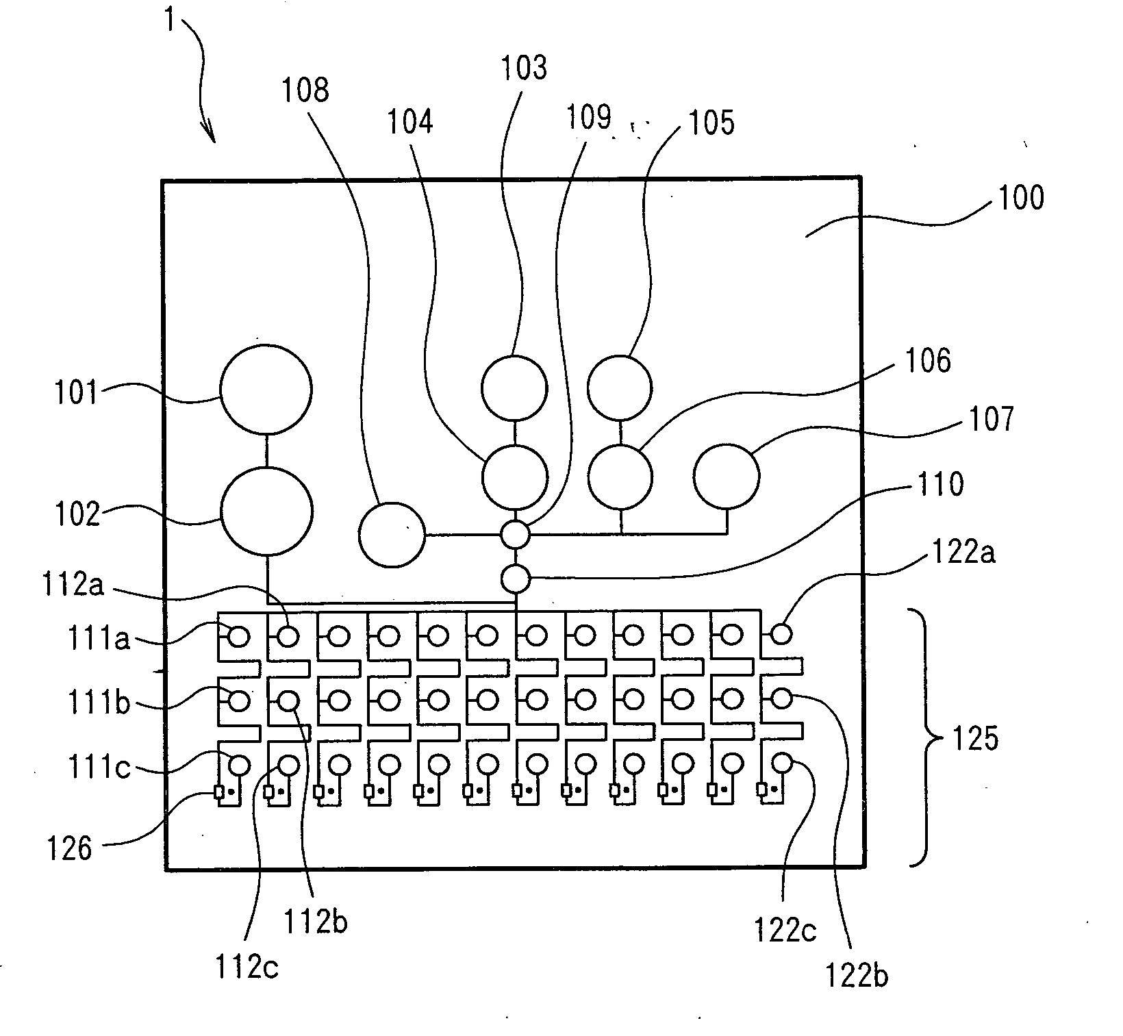
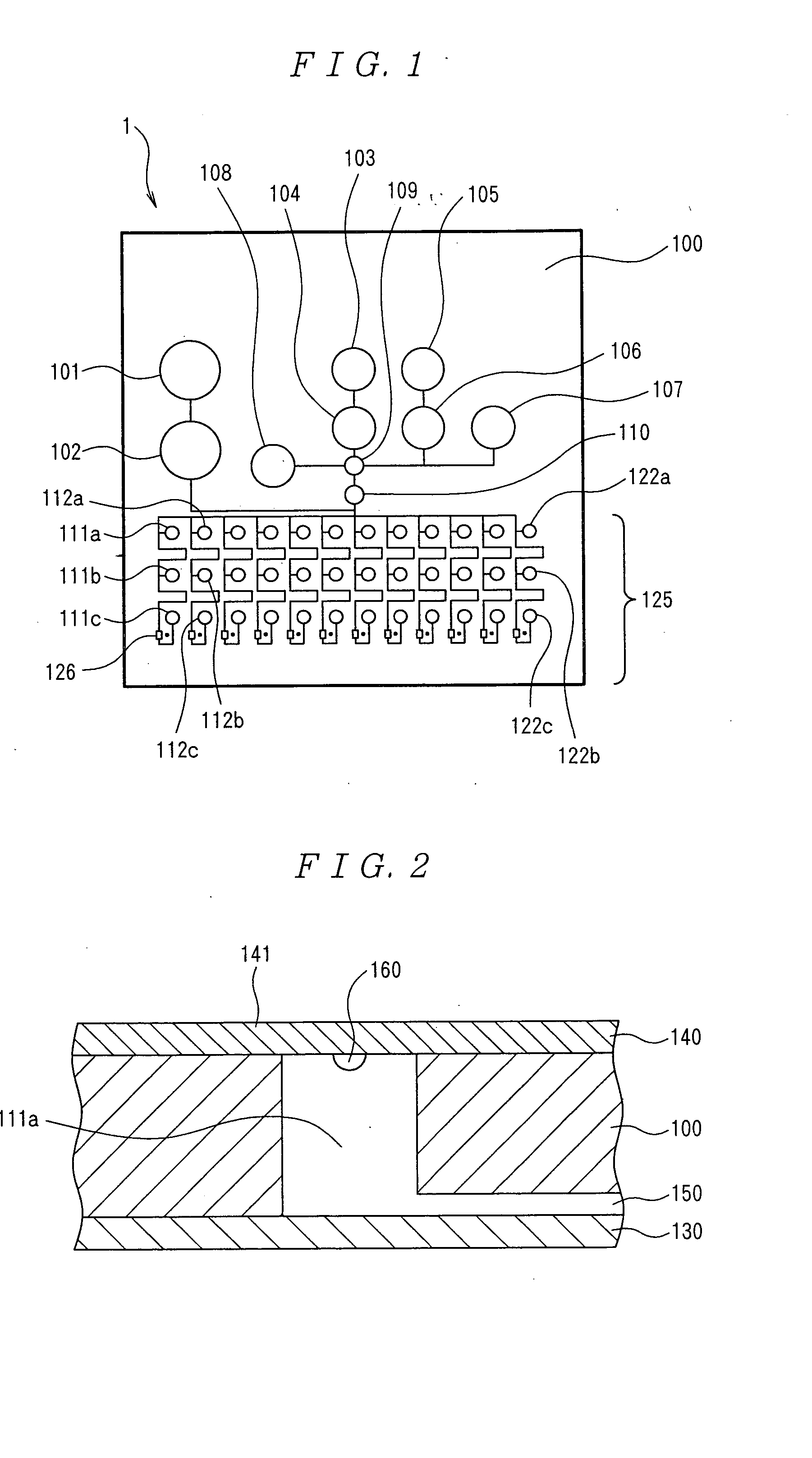
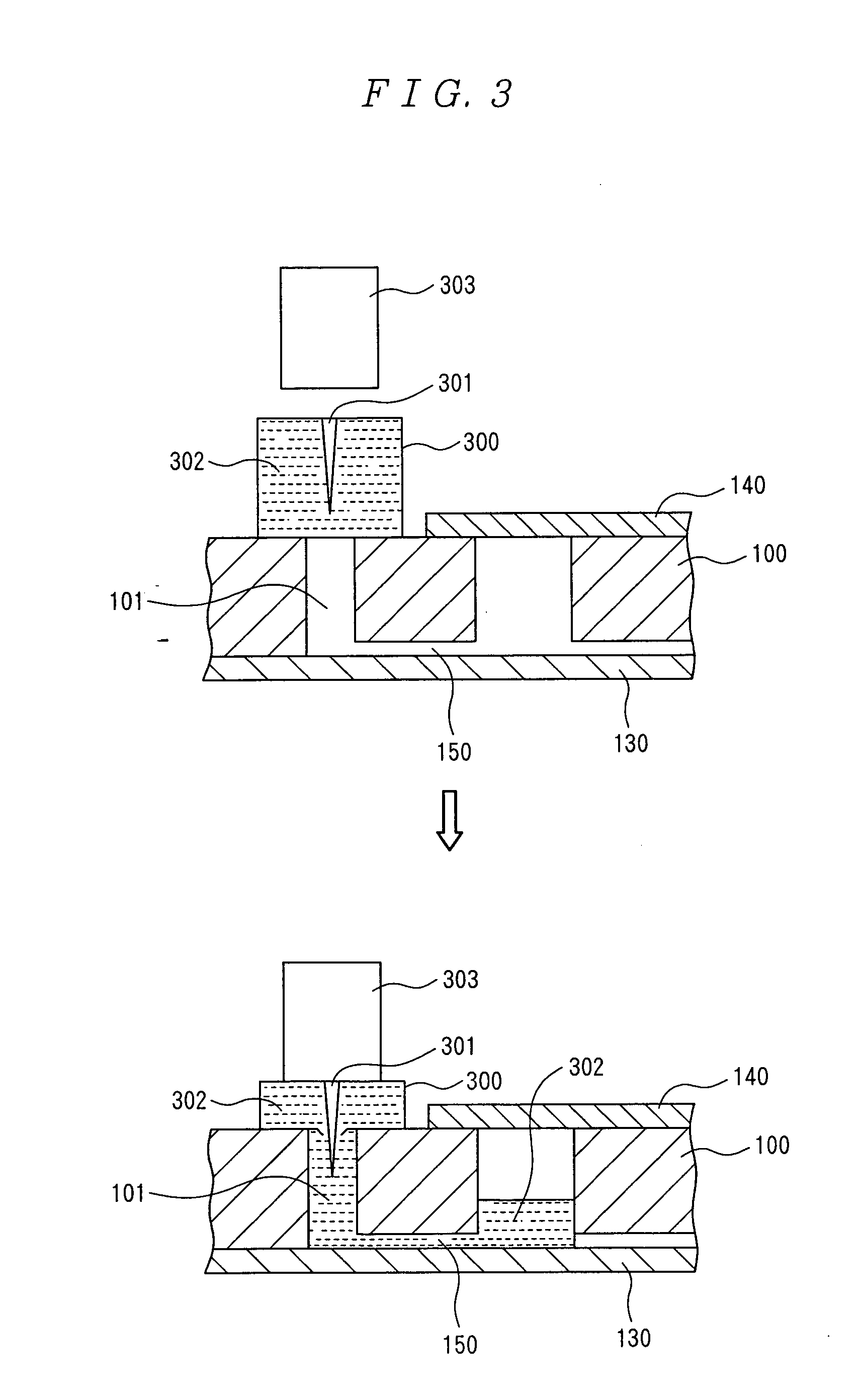
[0051] The analyzing cartridge having such a configuration can be produced inexpensively because the structure in the cartridge is simple, and is capable of treating a very small amount of liquid as in the case of μTAS. Also, by controlling the access of the gas to the above described vents, the flow of the liquid into or from the above described reservoirs through the above described capillaries can be controlled, thus making it possible to control the flow of the liquid into and from each reservoir in the analyzing cartridge without supplying the liquid from the outside of the analyzing cartridge and taking the liquid out to the outside thereof.
[0076] In addition, the liquid feed control device according to the present invention may control the outflow of the above described liquid from the above described reservoirs via the above described capillary by allowing or regulating the access of the gas to the above described reservoirs with the above described openings not covered with the above described vents.

Problems solved by technology

Also, there are possibilities that troubles occur such as spilling of liquid, clogging of the nozzle of the automatic pipetter and contamination due to insufficient cleaning, and analysis operators, particularly doctors and nurses in the case of POC analyses in the medical field, may significantly be burdened.
However, such a method is not suitable for quantitative analysis in a field of blood biochemistry and the like requiring a high level of accuracy.
However, when the amount of sample is as small as a few μl or so, a small amount of reagent solution and the like consistent with the small amount of sample should be encapsulated in a small bag, and the bag should be broken to leak the contents, and such operations are extremely difficult with the above described method.
For a method using a breakable seal like this, as in the case of the aforesaid method using a bag, if the amount of the encapsulated liquid sample is large ranging from a few hundred μl to a few ml, the liquid sample can be encapsulated easily and less expensively, but if the amount of the sample is as small as a few μl or so, the liquid sample becomes very small accordingly so that it will be extremely difficult to incorporate the breakable seal in the aforesaid small container, to inject and encapsulate a very small amount of liquid sample, to break the breakable seal, to take out the liquid sample and so on.
In the methods as described above, because the reagent and the buffer are encapsulated in the cartridge in liquid states, and a mechanism to take out the liquid such as a mechanism to break the seal is required, the cartridge needs to have a very complicated structure.
Also, for encapsulating the reagent in a liquid state and taking out the reagent into the reaction channel, a reagent of a few ten to a few hundred μl or more is required, and thus the cost for the reagent is increased.
In this method, the direction in which the liquid is fed is limited to one direction extending outwardly from the center of rotation, and rotation should be started / stopped accurately in the on / off of the feeding of liquids and so on, resulting in complicated designs for the feeding of liquids and channels.
In addition, there is also a disadvantage that the analyzer with which the cartridge is equipped to carry out measurements is complicated in structure and expensive.
Also, in any case, since the thickness of the capillary is in the order of millimeters, and thus a lager amount of sample is required, and the amount of reagent is increased in association therewith, the cost involved in analysis is no longer reduced, along with the aforesaid increase in the amount of liquid reagent encapsulated.
), and if one type of reagent is used, correlation with previous examination data may be poor, and quantitation itself may be difficult to carry out.
In other words, there is a disadvantage in terms of channel that the liquid and gas are flown in opposite directions in a very narrow channel.
In this method, the solid sample is dissolved in plasma itself while a reaction is carried out at the same time, but it is not easy to dissolve uniformly a solid reagent using 100% plasma in a very short time.
Also, there is the problem of vulnerability to contaminants (inhibiting substance) inhibiting analysis because the plasma is not diluted.
However, in this method of feeding the liquid, there is a disadvantage that the flow of the liquid can be controlled only linearly.
Those methods are used in the case where a solid phase antibody (antigen) is contacted with the sample as in immune-detecting reaction, but is not suitable for blood biochemical examination based on the reaction in a homogeneous system and examination of hazardous substances in the environment.
However, the amount of required blood sample is large, namely about 10 μl for each item of analysis, which means that one hundred and a few ten μl of blood is required in the case of measurements for ten items or more that are usually conducted in the blood biochemical examination.
Also, because the sample is contacted and reacted in succession with the reagent with which the filter paper or the like is impregnated, the type of analysis reactions is limited, and some of them are different from the aforesaid recommended methods defined by academic societies.
In addition, since the sample is not diluted, possibilities of being adversely influenced by contaminants in the sample are increased.
These techniques are not suitable for the POC analyses and the like where simplicity is required, because a container for the liquid reagent needs to be provided outside the chip, maintenance operations for replenishing the liquid reagent, removing clogs or performing cleaning in the connection between the chip and the container are required.
Otherwise, the liquid may be spilled out of the chip.
The above described vents always are opened outwardly, the feeding of the liquid is controlled by using pressure losses of the channel connected to the vents and providing pressure-relief openings with breakable seals, thus rising the problem of the structure being extremely complicated.

Method used


Image

  • Analyzing cartridge and liquid feed control device
  • Analyzing cartridge and liquid feed control device
  • Analyzing cartridge and liquid feed control device

Examples


experimental example 1

Measurement of Anti-Water Pressure of Hydrophobic Membrane

[0306] The anti-water pressure is measured at each average pore size for hydrophobic membranes of various kinds of materials. For the laboratory device for carrying out measurements, a device in which a disposable filter holder 810 with a membrane 800 set therein is attached to the tip of a syringe 820 with an inner diameter of 5 mm. The effective diameter of the membrane 800 is 3 mm. Furthermore, Figure (b) in FIG. 10 is a magnified sectional view of the filter holder 810 and the tip of the syringe 820.

[0307] For the measurement of anti-water pressure, the syringe 820 is first put in a test solution 830, and the syringe 820 is pushed against the a scale 840 while the syringe 820 is kept standing upright with its tip pointing upward, thereby carrying out a measurement. The air in the syringe 820 is pushed to the outside through the membrane 800, and a test solution 830 starts to seep through the membrane 800 if the syringe ...

experimental 2

Reagent Dissolving Adjuvant

[0311] Commercially available reagent kits for use in diagnosis of blood components were used to examine dissolving time of reagents. A large number of holes with the diameter of 2 mm were bore in a PMMA plate with thickness of 2 mm, a PTFE porous membrane was bonded to the one face of the PMMA plate in a same way as Example 4 described later, and 2 μl of each reagent solution was put in the hole, followed by air-drying the same for 2 hours. The reagent kits that were used are as follows. [0312] GOT, GPT: TA-LN Kainos (Kainos Co., Ltd.). [0313] ALP: ALP Kainos (Kainos Co., Ltd.). [0314]γGTP: EspaγGTP (N) (Nipro Co., Ltd.) and Aquaauto Kainos γGTP (Kainos Co., Ltd.). [0315] t-Bil: HA Test Wako (Wako Pure Chemical Industries, Ltd.) and Espa TB (Nipro Co., Ltd.). [0316] T. Chol: HA Test Wako (Wako Pure Chemical Industries, Ltd.). [0317] TG: HA Test Wako (Wako Pure Chemical Industries, Ltd.) and Aquaauto Kainos TG (Kainos Co., Ltd.). [0318] LDH: LDH Kainos (K...

example 1

[0328] An example in which quantitative analysis of total cholesterol in blood serum was carried out using an analyzing cartridge with two reagents of the total cholesterol detection kid (Trade Name: Cholesterol E-HA Test Wako manufactured by Wako Pure Chemical Industries, Ltd.), a reagent dissolving liquid and a diluent encapsulated therein, and the standard serum (Determiner for Measurement of Standard Serum Lipid manufactured by Kyowa Medix Co., Ltd.) was used as a calibration solution to correct the result of analysis will be described. Furthermore, for the method of feeding the liquid, a method using electroosomosis flows by application of voltage was used.

[0329] The analyzing cartridge 4 that was used and analysis operations will be described referring to the drawings. FIG. 11 shows a channel pattern of a plane member 900, and FIG. 12 shows the back face (face provided with no grooves) of the plane member 900 of FIG. 11. And, FIG. 13 is a sectional view of a portion of a reag...


PUM


Abstract

An analyzing cartridge and method for using it to analyze a sample having a plurality of reservoirs and capillaries connected for communication between these reservoirs and is provided therein with a reagent required for analysis. The reservoirs are provided with openings leading to the outside of the cartridge, and the openings are covered with vents each consisting of a gas-permeable / non-liquid-permeable, hydrophobic, porous membrane. The analyzing cartridge requires only trace amounts of a sample and a reagent and no maintenance. It is provided with a non-fluid reagent in vent-carrying reservoirs thereby making it possible to formulate a very trace amount of reagent solution in the cartridge by injecting a reagent dissolving liquid into the reservoirs immediately before analyzing. A liquid feed control device controls the feeding of the liquid between the reservoirs via the capillaries when it is attached to the cartridge to allow or control the entry / exit of air via the vents.

Description

TECHNICAL FIELD [0001] The present invention relates to an analyzing cartridge for use in analysis of a trace amount of sample, enabling analysis and detection to be carried out conveniently, and a method for producing the same. The invention also relates to an analysis method using the analyzing cartridge. In addition, the invention relates to a liquid feed control device that is attached to the analyzing cartridge, and controls the feeding of liquid in the analyzing cartridge. BACKGROUND ART [0002] Attention is being given to the importance of analyses and measurements carried out at or near the site where the analyses and measurements are required (hereinafter referred to as “POC (point of care) analyses and the like” collectively), such as analyses for bedside diagnosis (POC analyses) in which a measurement required for medical diagnosis is carried out near a patient, analyses of hazardous substances in rivers and wastes carried out at sites such as rivers and wastes treatment p...

Claims


Application Information

Patent Timeline
IPC IPC(8): B01L3/00G01N33/487G01N33/49G01N35/10
CPCB01L3/502715Y10T436/2575B01L3/50273B01L3/502738B01L3/523B01L2200/027B01L2200/0621B01L2200/0684B01L2200/148B01L2200/16B01L2300/047B01L2300/0672B01L2300/0816B01L2300/0864B01L2300/0867B01L2300/087B01L2300/0887B01L2400/0415B01L2400/0418B01L2400/0481B01L2400/0487B01L2400/0683B01L2400/0694G01N2035/1044B01L3/502723G01N35/10
Inventor KITAGUCHI, NOBUYAKIGUCHI, AKIRA
Owner ASAHI KASEI KK
Learn More