Timing of intra-aortic balloon pump therapy

a technology of intra-aortic balloon and timing, which is applied in the direction of prosthesis, therapy, diagnostic recording/measuring, etc., can solve the problems of persistent late timing, subject to operator error, and frequent adjustment and monitoring of iabp therapy by an operator

Active Publication Date: 2005-07-07
DATASCOPE
View PDF8 Cites 38 Cited by
  • Summary
  • Abstract
  • Description
  • Claims
  • Application Information

AI Technical Summary

Benefits of technology

[0023] The process for determining time delays may further include the step of determining a duration interval between the actual inflate command time and the deflate command time, and if the duration interval is less than a predetermined time interval, the deflate command time may be adjusted so that the duration interval is at least as large as the predetermined time interval.
[0024] The process for determining time delays may be repeated for a plurality of inflation / deflation cycles. In each inflation / deflation cycle the dither time interval added to the nominal inflate command time may be different from the dither time interval added to the nominal inflate command time in other inflation / deflation cycles. In such event, the analyzing step may include averaging the blood pressure data acquired during the plurality of inflation / deflation cycles on a time-aligned point-by-point time basis to obtain an ensemble average, and analyzing the ensemble average to determine an average realization time at which the effects of inflating the inflatable chamber are realized on the blood pressure waveform. The step of determining the delay time may include determining a time-aligned inflate command time based on the actual inflate command time for each of the inflation / deflation cycles and determining a time interval between the time-aligned inflate command time and the average realization time.

Problems solved by technology

Despite the improvements in operation achieved through partial automation of the inflation and deflation timing, IABP therapy still requires frequent adjustment and monitoring by an operator, and is subject to operator error both at startup and during periodic adjustment.
If the commands to inflate or deflate the balloon are issued at the time these cardiac events are detected, the resultant timing would be persistently late.
This is a consequence of the delays that are inherent in IABP systems.
For example, if the balloon inflation cycle is initiated at the time the dicrotic notch is detected, the intrinsic time delays in the IABP system would result in a late augmentation of the aortic blood pressure.
Similarly, if the balloon deflation cycle is initiated at the time the end of the diastolic interval is detected, the intrinsic time delays would cause complete deflation of the balloon to occur too late.
Although the use of earlier surrogates to predict the occurrence of these cardiac events has been considered, such surrogates have generally proven to be unreliable.
One source of delay is the electro-pneumatic delay associated with the activation of valves, the pressurization of pneumatic volumes and the movement of the shuttle gas to begin inflation or deflation of the balloon, all of which follow a balloon inflation or deflation command.
Another source of delay is the time for the shuttle gas to move substantially into (i.e., inflate) or out from (i.e., deflate) the balloon.
Yet a further delay is the time from the closing of the aortic valve until the aortic pressure change resulting from that event (i.e., the dicrotic notch) is propagated to the blood pressure monitoring site.
Still another source of delay is the time it takes the pressure signal to propagate from the monitoring site until its conversion into an electrical signal.
The delays associated with propagating changes in aortic pressure from the aortic valve to the blood pressure monitoring site and with propagating pressure signals from the monitoring site until they are converted into electrical signals, however, are highly variable.
There also may be other variable or constant intrinsic delays in an IABP system.
Errors in these estimates may result in actual delays that are greater than or less than the estimated values.

Method used


Image

  • Timing of intra-aortic balloon pump therapy
  • Timing of intra-aortic balloon pump therapy
  • Timing of intra-aortic balloon pump therapy

Examples


Embodiment Construction

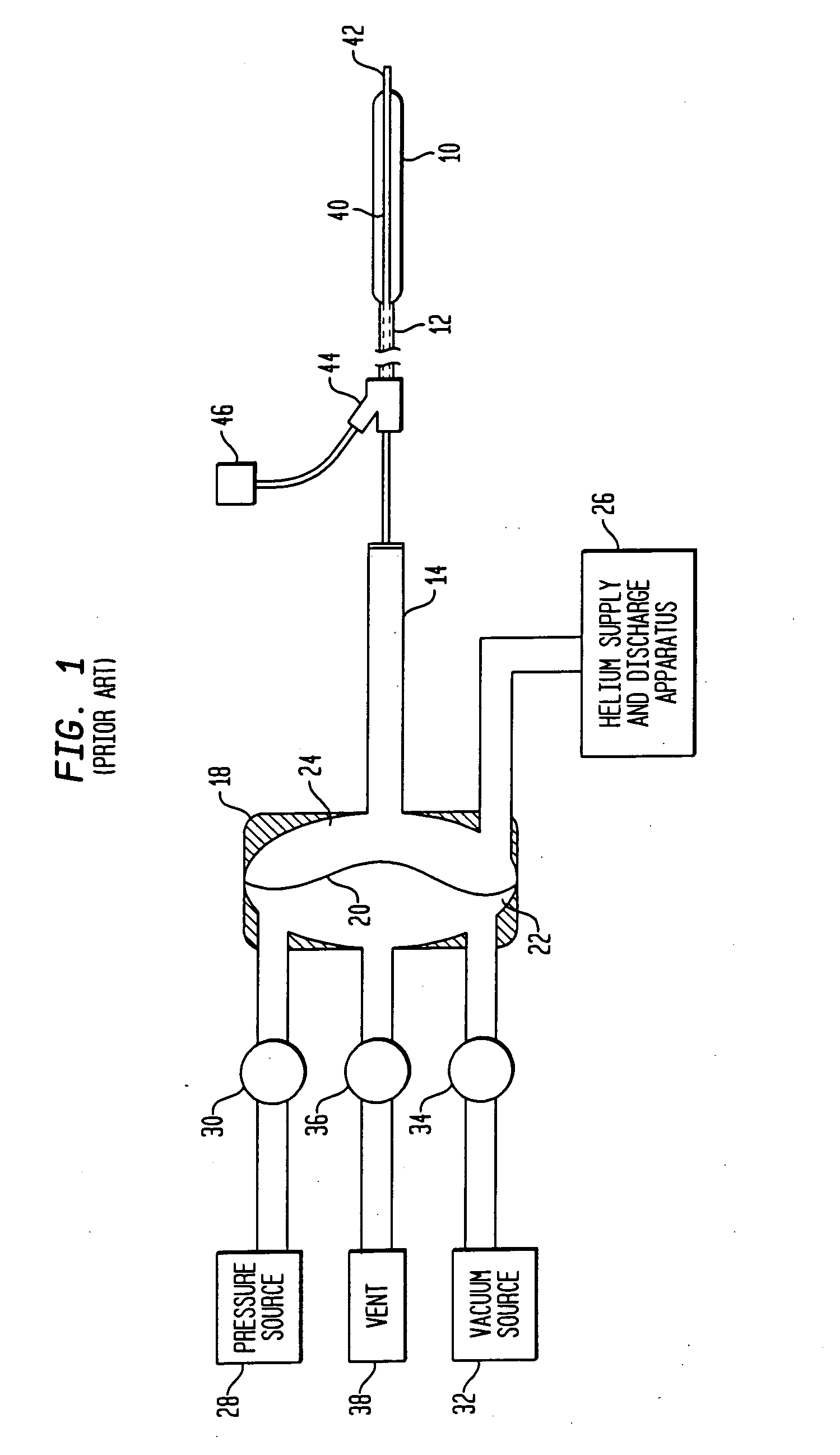
[0037] The present invention relates to a method for controlling the timing of a cardiac assist device in a patient in order to optimize diastolic augmentation. Various diastolic augmentation systems and devices are currently known. For example, the present invention may be used to control inflation and deflation of a balloon that is permanently or temporarily disposed in the descending aorta of a patient. Such devices, including that shown schematically in FIG. 1, are well known in the art, and therefore a detailed description of their structure and operation is omitted.

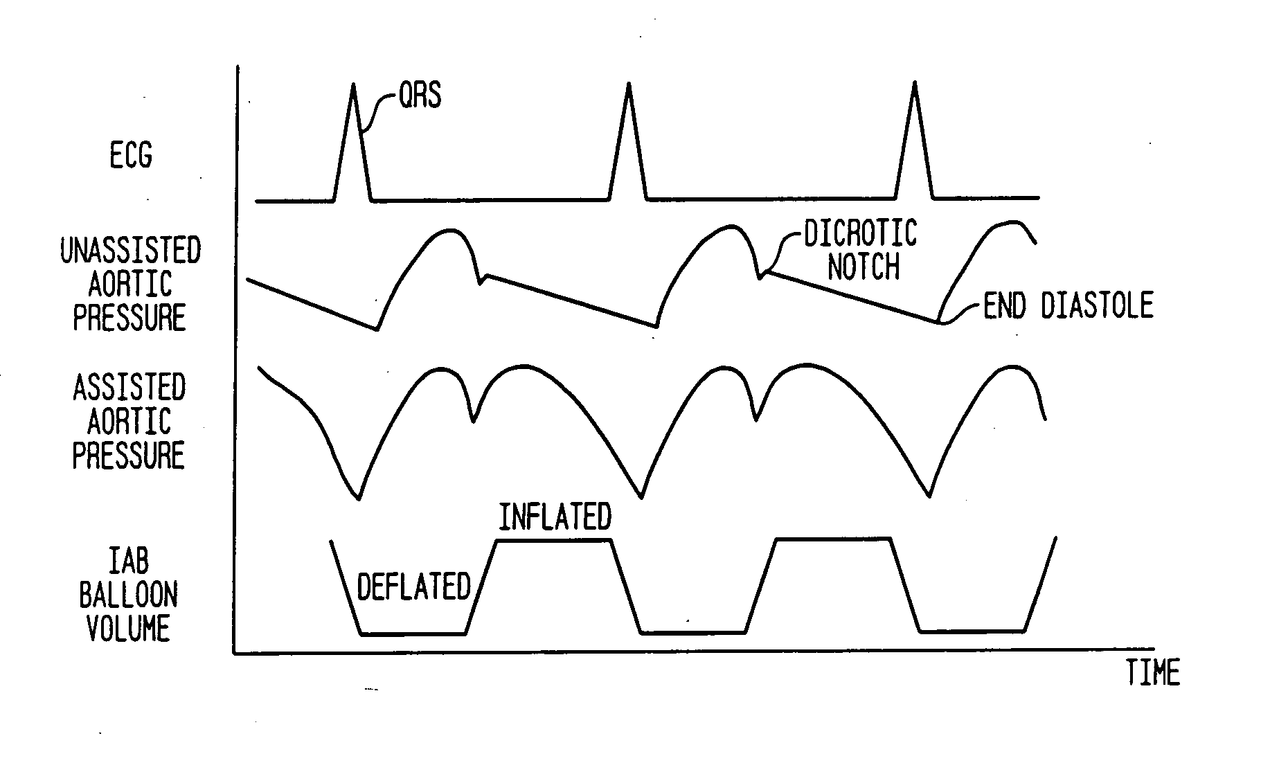
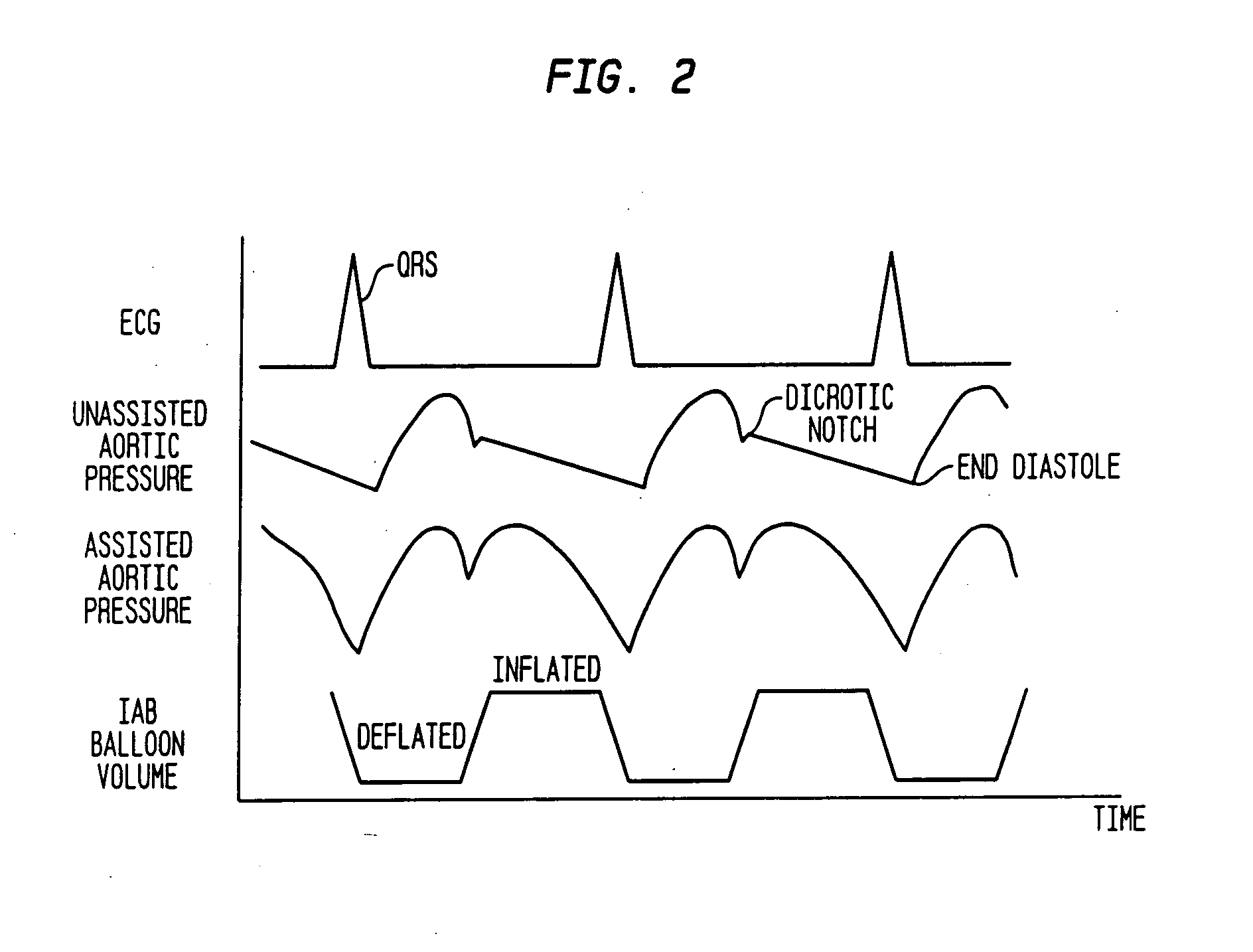
[0038] During IABP therapy, balloon inflation occurs in real time. However, the effect of inflation as shown on the aortic blood pressure waveform is not seen in real time. Rather, there is a delay between the time at which the balloon inflation command is issued and the time at which the pressure augmentation resulting from balloon inflation is seen on the aortic blood pressure waveform. This delay consists of the...


PUM


Abstract

In order to fully automate the inflation timing and deflation timing of an intra-aortic balloon pump, certain delays intrinsic in the system must be taken into account. A process for calculating these delays includes determining a nominal inflate command time, adding a dither time interval to the nominal inflate command time to obtain an actual inflate time, and determining a deflate command time. An inflation/deflation cycle is then processed in which the intra-aortic balloon pump is inflated at the actual inflate command time and deflated at the deflate command time. Blood pressure data is acquired from the patient during the inflation/deflation cycle, and is then analyzed to determine a realization time at which the effects of inflating the intra-aortic balloon are realized on the blood pressure waveform. From this the total delay time between the actual inflate command time and the realization time can be determined.

Description

CROSS-REFERENCE TO RELATED APPLICATIONS [0001] This application claims the benefit of the filing date of U.S. Provisional Patent Application No. 60 / 498,871 filed Aug. 29, 2003, the disclosure of which is hereby incorporated herein by reference.BACKGROUND OF THE INVENTION [0002] The present invention relates generally to intra-aortic balloon pump therapy, and more particularly, to systems for inflating and deflating intra-aortic balloons. Still more particularly, the present invention relates to methods for use in setting the timing of the balloon inflation and deflation cycles in intra-aortic balloon-pump therapy. [0003] Intra-aortic balloon pump (IABP) therapy is a form of temporary cardiac assist which is frequently prescribed for patients who have suffered a heart attack or some other form of heart failure. In such therapy, a thin balloon is inserted, typically through the femoral artery, into the patient's descending aorta. The balloon is connected through a series of thin tubes...

Claims


Application Information

Patent Timeline
Patent Type & Authority Applications(United States)
IPC IPC(8): A61M1/10A61M1/12
CPCA61M1/1037A61M1/106A61M1/1072A61M1/125A61M2230/04A61M2230/30A61M1/1086A61M60/274A61M60/497A61M60/139A61M60/531A61M60/295
Inventor NIGRONI, PAULPRAIS, BRIANFREAMON, ROBERT
Owner DATASCOPE
Why Eureka
Try Eureka