Methods and apparatus for anchoring an occluding member

a technology of occlusion member and anchoring device, which is applied in the direction of catheters, applications, other blood circulation devices, etc., can solve the problems of undesirable use of external cross-clamps, and achieve the effects of optimizing inflation pressure, high friction, and high friction portions

Inactive Publication Date: 2005-07-07
VALLEY KIRSTEN L +3
View PDF77 Cites 294 Cited by
  • Summary
  • Abstract
  • Description
  • Claims
  • Application Information

AI Technical Summary

Benefits of technology

[0033] The first portion is preferably integrally formed with the second portion and is provided with a number of ribs and/or a selective coating. A method of providing a selective coating and other methods of providing a frictional surface are described in PCT Application Number PCT/US94/09489 which is incorporated herein by reference. Another method of providing high and low friction portions would be to mask the low friction portion and sandblast the high friction portion. Alternatively, a mandrel which is used to make the balloon may have the high friction portion sandblasted.
[0034] The present invention provides distinct advantages over PCT Application Number PCT/US94/09489 since the radially-extending arms help prevent the high friction portions from contacting the blood vessel. A problem which might occur with the balloon of PCT/US94/09489 is that the balloon might unravel when the balloon is inserted into the patient thereby exposing the high friction portions. Conversely, if the balloon is wrapped too tight, the balloon may not open correctly when the balloon is inflated. The present invention provides high friction portions which are exposed but prevented from contacting the body passageway by the radially outward portion of the arms.
[0035] In another aspect of the invention, pressure sensors are provided on both sides of the balloon for measuring pressures exerted on the balloon. In this manner, it can be determined when a pressure differential exists across the expandable member which might move the balloon upstream or downstream. The pressure sensors are preferably coupled to an alarm which indicates when the pressure differential exceeds a predetermined threshold pressure. In a preferred embodiment, the pressure of cardioplegic fluid in the ascending aorta is adjusted to reduce the pressure differential to a value below the threshold pressure. The descriptive terms downstream and upstream refer to the direction of blood flow and the direction opposite normal blood flow, respectively. In the arterial system, downstream refers to the direction away from the heart and upstream refers to the direction toward to the heart. The terms proximal and distal, when used herein in relation to instruments used in the procedu...

Problems solved by technology

First, such isolation facilitates infusion of cardioplegic fluid into the coronary arteries to perfuse the myocardium and arrest cardiac function without allowing the cardioplegic fluid to be distributed elsewhere in the patient's circulatory system.
Second, such isolation facilitates use of a cardiopulmonary bypass system to maintain circulation of oxygenated blood throughout the circulatory s...

Method used


Image

  • Methods and apparatus for anchoring an occluding member
  • Methods and apparatus for anchoring an occluding member
  • Methods and apparatus for anchoring an occluding member

Examples


Embodiment Construction

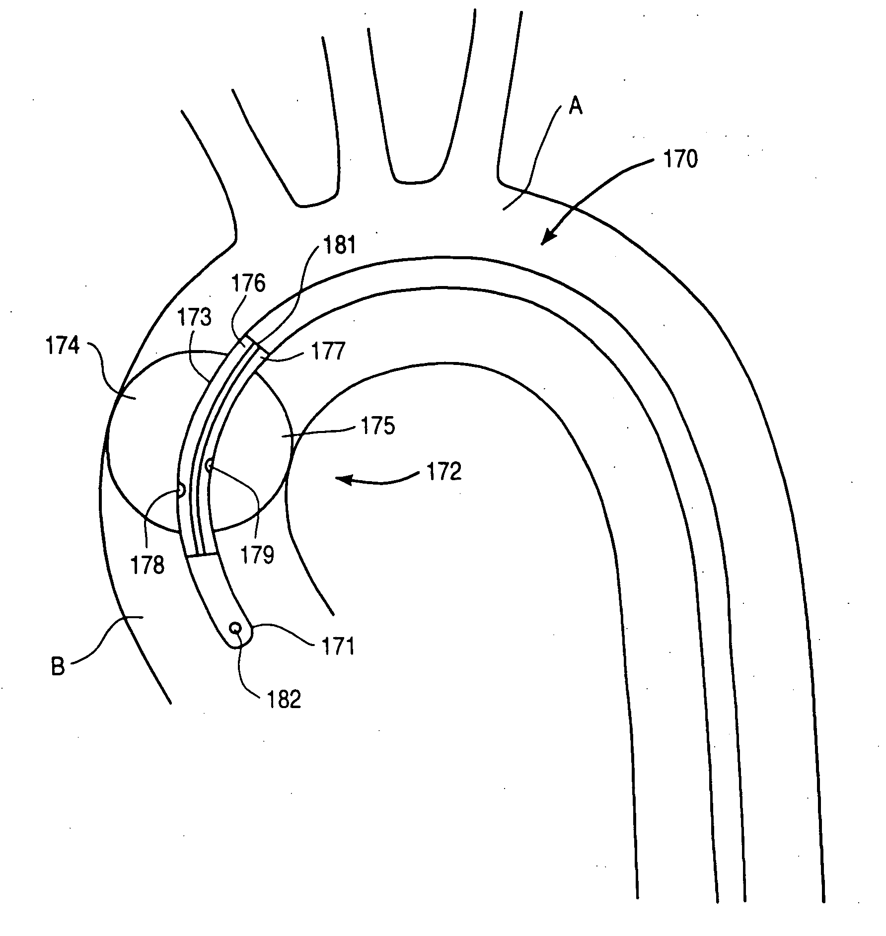
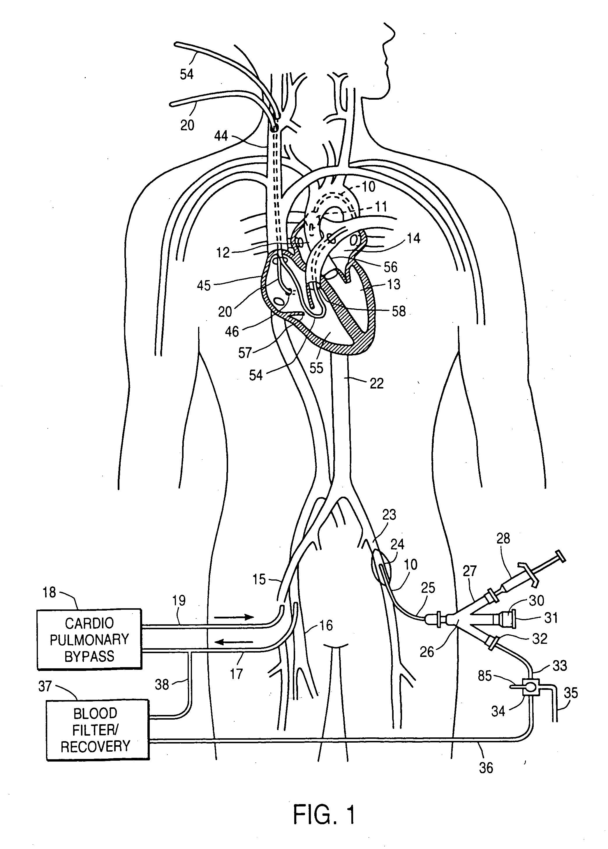
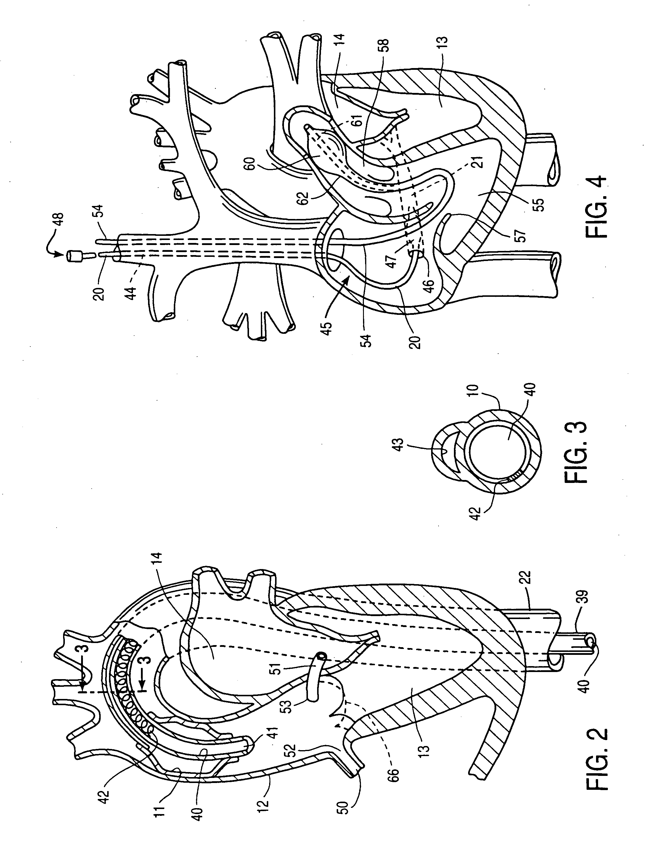
[0091] The invention provides a cardiac access system including an endovascular device for partitioning the ascending aorta, as well as a system for selectively arresting the heart, which are useful in performing a variety of cardiovascular, pulmonary, neurosurgical, and other procedures. The procedures with which the invention will find use include repair or replacement of aortic, mitral, and other heart valves, repair of septal defects, pulmonary thrombectomy, electrophysiological mapping and ablation, coronary artery bypass grafting, angioplasty, atherectomy, treatment of aneurysms, myocardial drilling and revascularization, as well as neurovascular and neurosurgical procedures. The invention is especially useful in conjunction with minimally-invasive cardiac procedures, in that it allows the heart to be arrested and the patient to be placed on cardiopulmonary bypass using only endovascular devices, obviating the need for a thoracotomy or other large incision. Moreover, even in c...


PUM

PropertyMeasurementUnit
Forceaaaaaaaaaa
Pressureaaaaaaaaaa
Volumeaaaaaaaaaa

Abstract

Pressure is measured on both sides of an occluding member for determining when pressure forces on the occluding member may cause migration of the occluding member. An alarm indicates when the pressure force on the balloon exceed a predetermined threshold. In another aspect of the invention, a pressure monitor determines when a rate of pressure increase with respect to the fluid volume in the balloon reaches a predetermined threshold when inflating the occluding member. A predetermined amount of fluid is then added to the balloon so that the balloon is not under inflated or over inflated.

Description

CROSS-REFERENCE TO RELATED APPLICATIONS [0001] This application is a divisional of U.S. patent application Ser. No. 08 / 570,286, filed Dec. 11, 1995, which is a continuation-in-part of Ser. No. 08 / 486,216, filed Jun. 7, 1995 which is a continuation-in-part of application of copending U.S. patent application Ser. No. 08 / 282,192, filed Jul. 28, 1994, which is a continuation-in-part of application Ser. No. 08 / 162,742, filed Dec. 3, 1993, which is a continuation-in-part of application Ser. No. 08 / 123,411, filed Sep. 17, 1993, which is a continuation-in-part of application Ser. No. 07 / 991,188, filed Dec. 15, 1992, which is a continuation-in-part of application Ser. No. 07 / 730,559, filed Jul. 16, 1991, which issued as U.S. Pat. No. 5,370,685 on Dec. 6, 1994. This application is also related to copending U.S. patent application Ser. No. 08 / 159,815, filed Nov. 30, 1993, which is a U.S. counterpart of Australian Patent Application No. PL 6170, filed Dec. 3, 1992. This application is also rela...

Claims


Application Information

Patent Timeline
IPC IPC(8): A61B17/00A61B17/12A61B19/00A61F2/24A61F2/958A61M1/36A61M25/00A61M25/01A61M25/02A61M25/06A61M29/02
CPCA61B17/12022A61M1/3659A61B17/12045A61B17/12109A61B17/12136A61B2017/00243A61B2018/00232A61B2018/00261A61B2019/464A61B2019/5206A61F2/2427A61M1/3653A61M25/0028A61M25/0032A61M25/0041A61M25/0054A61M25/0125A61M25/0147A61M25/0152A61M25/0155A61M25/02A61M25/0662A61M25/10A61M25/1002A61M25/1006A61M25/1027A61M25/1029A61M25/1034A61M2025/0002A61M2025/0031A61M2025/0034A61M2025/0046A61M2025/0078A61M2025/015A61M2025/0161A61M2025/028A61M2025/1031A61M2025/1047A61M2025/1052A61M2025/1059A61M2025/1077A61M2025/1095A61M2202/047A61M2205/11A61M2205/366A61M2210/125A61M2210/127A61B17/12036A61B2090/064A61B2090/306A61M1/3613
Inventor VALLEY, KIRSTEN L.SNOW, DAVID W.FAN, SYLVIA W.MUELLER, RICHARD L. JR.
Owner VALLEY KIRSTEN L
Why Eureka
Try Eureka