

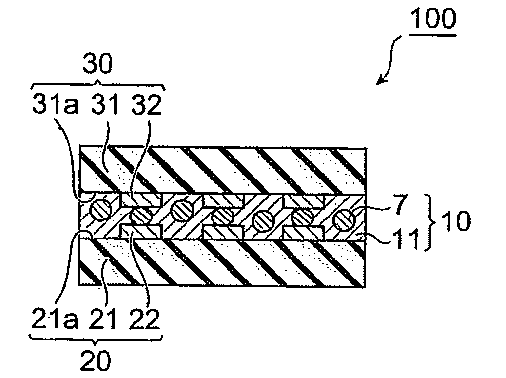
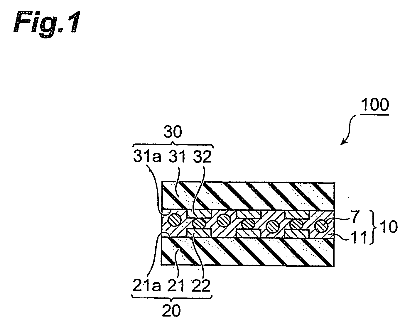
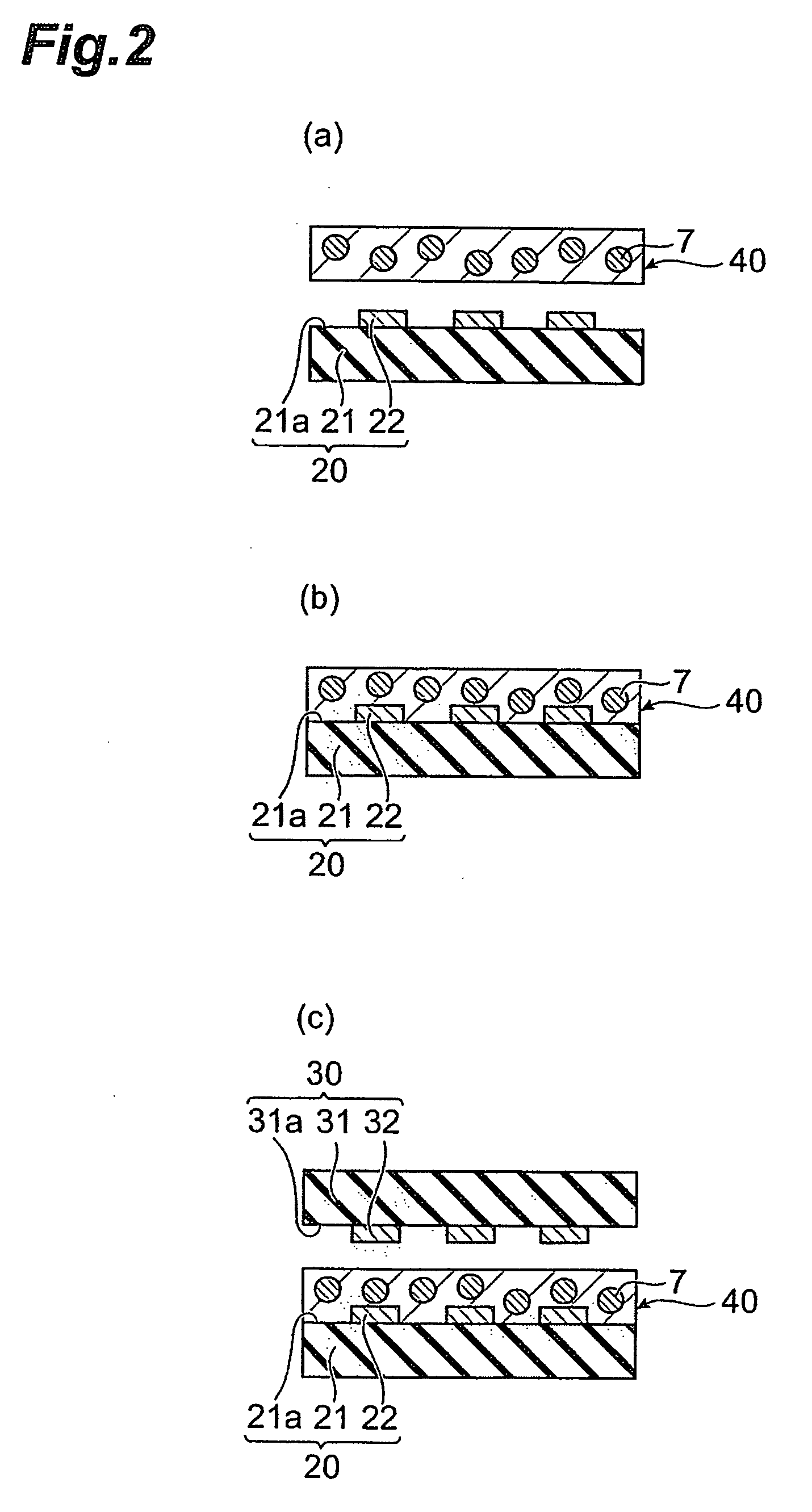
Adhesive film for circuit connection, and circuit connection structure
a technology of adhesive film and circuit connection, applied in the direction of film/foil adhesive without carrier, film/foil adhesive, branching pipes, etc., can solve the problems of poor connection processability of adhesive film for circuit connection with radically polymerizable substance, film accuracy failure, flexible substrate as a circuit member becomes unlikely to drop with vibration, etc., to reduce the cost of the circuit connection structure, improve the processability, and improve the effect of connection
- Summary
- Abstract
- Description
- Claims
- Application Information
AI Technical Summary
Benefits of technology
Problems solved by technology
Method used
Image

Examples
example 1
[0060] Mixed into 130 parts by weight of a solution containing 40% by weight of a phenoxy resin (weight-average molecular weight: 45,000) dissolved in a 50:50 mixed solvent of toluene and ethyl acetate were 10 parts by weight of urethane acrylate having the viscosity at 25° C. of 250,000 mPa.s, 25 parts by weight of bis(acryloxyethyl) isocyanurate having the viscosity at 25° C. of 8,000 mPa.s, 10 parts by weight of dimethylol tricyclodecane diacrylate having the viscosity at 25° C. of 150 mPa.s, and 3 parts by weight of 2-methacryloyloxy ethyl acid phosphate as the radically polymerizable substance, and 4 parts by weight of a hydrocarbon-diluted solution containing 50% by weight of 2,5-dimethyl-2,5-bis(2-ethylhexanoylperoxy)hexane as a free radical generator. Thereafter, this mixture was uniformly stirred. Furthermore, mixed and dispersed in this mixture was 3% by volume of conductive particles with the average particle size of 5 μm formed by providing surfaces of polystyrene-core p...
PUM
| Property | Measurement | Unit |
|---|---|---|
| viscosity | aaaaa | aaaaa |
| temperature | aaaaa | aaaaa |
| temperature | aaaaa | aaaaa |
Abstract
Description
Claims
Application Information