Motor control device

Active Publication Date: 2005-07-14
BROTHER KOGYO KK
View PDF18 Cites 15 Cited by
  • Summary
  • Abstract
  • Description
  • Claims
  • Application Information

AI Technical Summary

Benefits of technology

[0045] The present invention can be applied to the driving target of the DC motor that is rotated or linearly driven. The present invention works significantly well if the driv

Problems solved by technology

However, only switching the gain according to the driving load of the DC motor, as in the above disclosure, may cause deterioration in control performance in a case where there is a sharp fluctuation in the driving load.
However, a significant change in the load of the DC motor that dr

Method used


Image

  • Motor control device
  • Motor control device
  • Motor control device

Examples


first embodiment

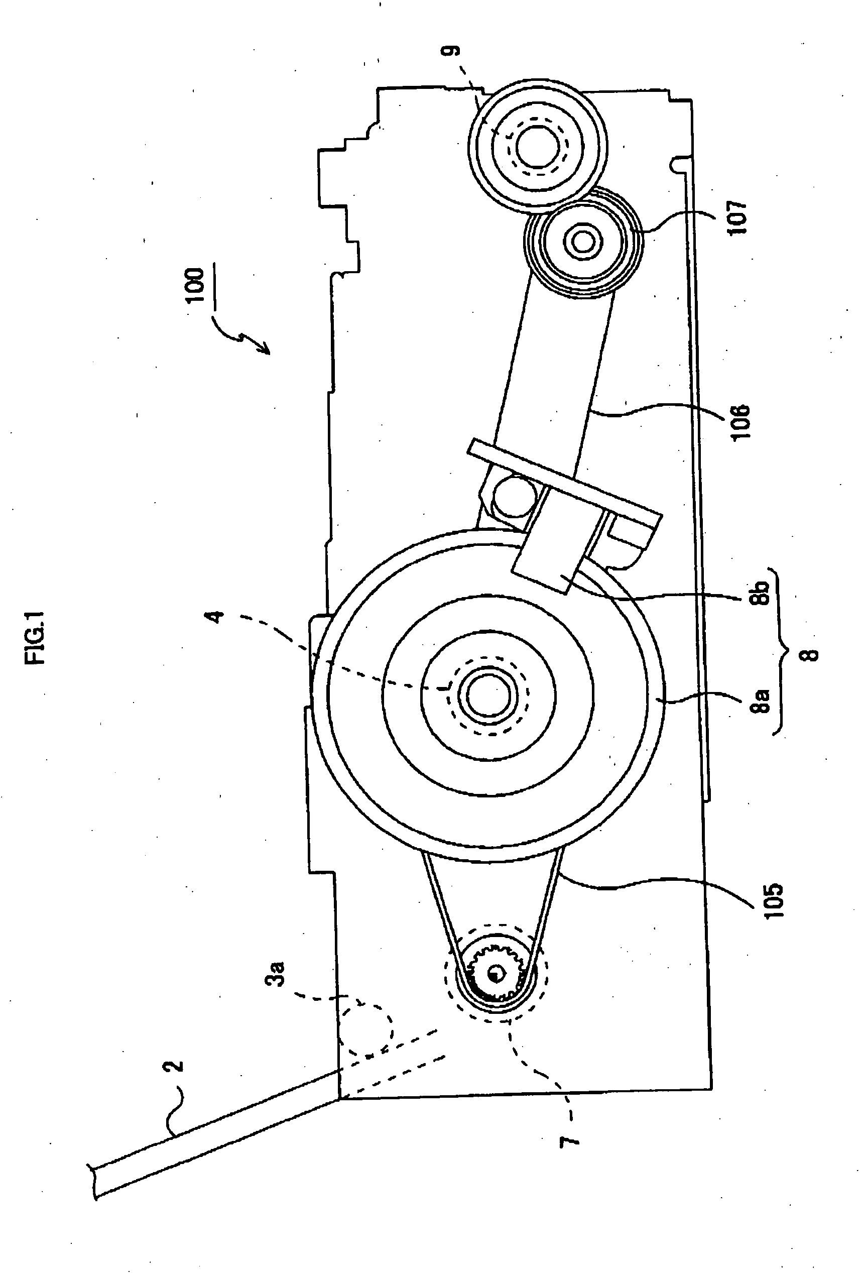
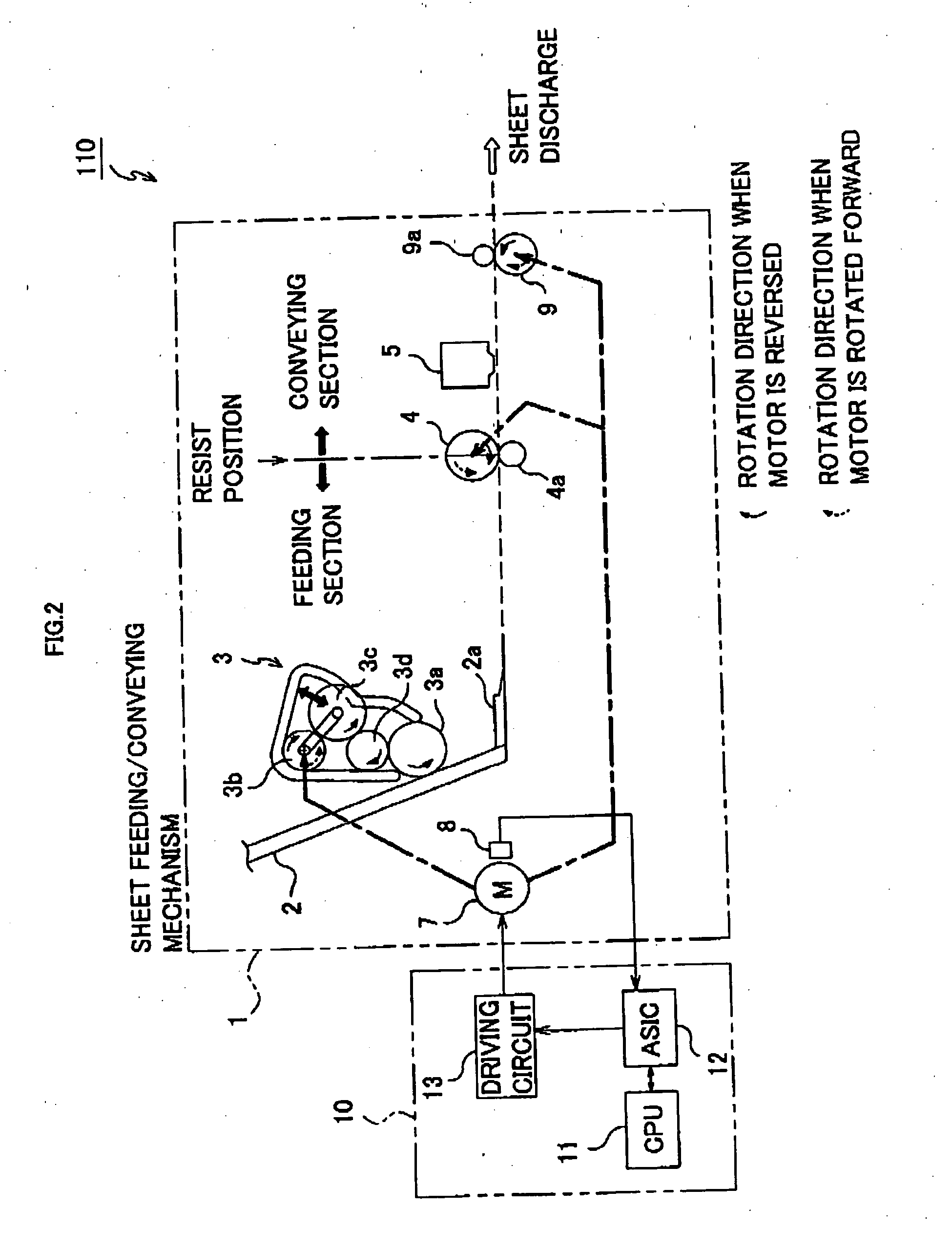
[0069] Referring to FIG. 1, a printer 100 of the present embodiment mainly comprises a sheet storing board 2 that stores stacked sheets for recording, a feeding roller 3a that delivers the sheets stacked on the sheet storing board 2 one by one, a conveying roller 4 that conveys the sheet delivered by the feeding roller 3a at the time of recording, a discharge roller-9 that assists sheet conveyance during the recording and discharges the sheet after completion of the recording, an LF (Line Feed) motor 7 that is a rotary drive source of the feeding roller 3a, the conveying roller 4 and the discharge roller 9, and a rotary encoder 8 (hereafter, referred to as an “encoder”) constituted of a rotary slit board 8a that rotates with rotation of the conveying roller 4 and a photo interrupter 8b. The LF motor 7 (hereafter, referred to as a “motor”) is a DC motor.

[0070] The motor 7 rotates the conveying roller 4 and the rotary slit board 8a via a belt 105 connecting the motor 7 and a driving ...

second embodiment

[0130] In the first embodiment, an appropriate observer is selected according to the fluctuations in the load amount of the motor 7. Thereby, high control performance is maintained in the state feedback control using the state estimator OBS. However, under the conditions that merely the observer is switched according to the load level, the manipulation amount u is increased as the load amount is increased, as can be clearly seen in FIG. 10c.

[0131] An increase in the manipulation amount u may lead to an increase in power consumption of the whole apparatus, and further to an increase of a capacity of the power source. Or, deterioration in stopping accuracy may occur. Depending on the type of the control system, it may not be desirable that the manipulation amount u is increased so much.

[0132] In the present embodiment, not only the observer but also the control gain is switched according to the load level so that too much increase is inhibited in the manipulation amount u even if th...

third embodiment

[0152] In the first and second embodiments, the load of the motor 7 is determined (estimated) based on the manipulation amount u. However, the load of the motor 7 is varied depending on the ambient temperature, for example. In the present embodiment, the load is determined based on the ambient temperature instead of the manipulation amount u. It is assumed that the lower the ambient temperature is, the heavier the load of the motor 7 becomes. Therefore, when the ambient temperature is higher than a predetermined temperature threshold, the normal load observer is selected. When the ambient temperature is lower than the predetermined temperature, the normal load observer is switched to the high load observer.

[0153] As shown in FIG. 20, a motor control device 70 of the present embodiment which performs the above switching comprises a thermistor 73 that outputs a sensor signal corresponding to the ambient temperature, and a temperature detector 74 that detects the ambient temperature b...


PUM


Abstract

In a motor control device controlling a motor by a state feedback control, high control accuracy is maintained regardless of fluctuations in a motor load so as to improve control performance of the state feedback control. A control signal (manipulation amount) outputted from a feedback calculator for controlling the motor is compared to a manipulation threshold set to a manipulation threshold setting register so as to determine the magnitude of a load amount of the motor. The feedback calculator includes an observer and performs the state feedback control of the motor. When the load amount is in normal level, a normal load observer matrix set in an observer table is selected to configure a normal load observer. When the load amount is increased, a high load observer matrix is selected to configure a high load observer.

Description

BACKGROUND OF THE INVENTION [0001] i) Technical Field of the Invention [0002] This invention relates to a control device of a motor, which estimates an operating state of a control target using a state estimator (observer), for example, and controls the motor by a feedback control based on the estimation. [0003] ii) Description of the Related Art [0004] Heretofore, an image forming apparatus, such as a printer and a facsimile, has been provided with a conveying device that conveys a sheet fed by a feeding device, as an image forming by an image forming unit, like a record head, onto the sheet proceeds. This type of conveying device comprises a conveying roller that is brought into frictional contact with the sheet to convey the same, and a driving source, such as a motor, that rotationally drives the conveying roller. The conveying device regulates a rotation amount of the conveying roller according to operating instructions to convey the sheet from the outside. As the sheet is conv...

Claims


Application Information

Patent Timeline
IPC IPC(8): H02P29/00G05D3/12
CPCH02P23/005H02P23/18
Inventor AKIYAMA, SHIGEKI
Owner BROTHER KOGYO KK
Why Eureka
Try Eureka