
Optical device utilizing plasmon resonance

a technology of optical devices and plasmons, applied in the field of optical devices, can solve problems such as impairment of the functions of the device for use with the sensor, deterioration of the character of each device, and impairment of the essential functions of the devi

Inactive Publication Date: 2005-07-14
FUJIFILM HLDG CORP +1
View PDF20 Cites 14 Cited by
  • Summary
  • Abstract
  • Description
  • Claims
  • Application Information

AI Technical Summary

Benefits of technology

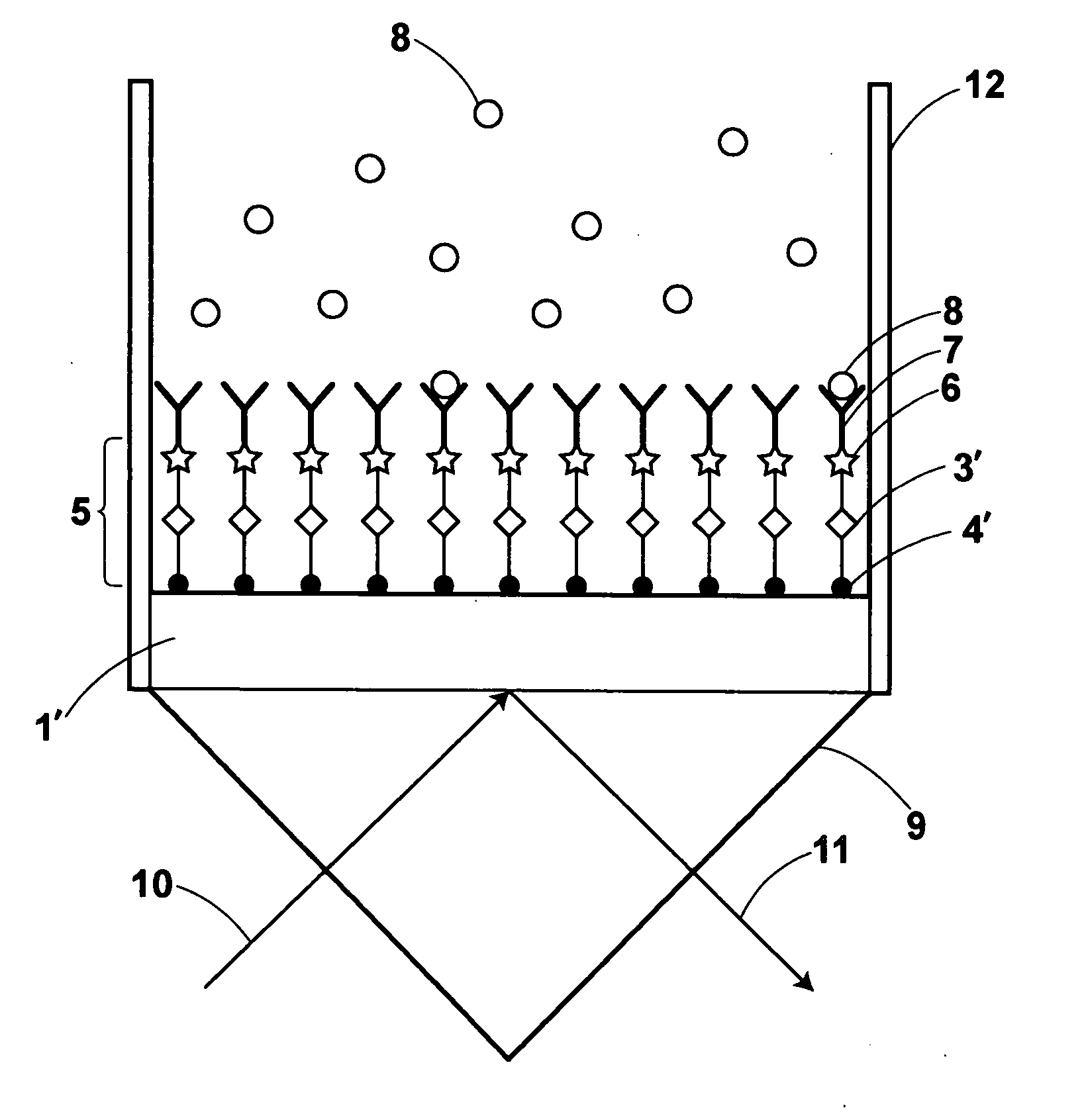
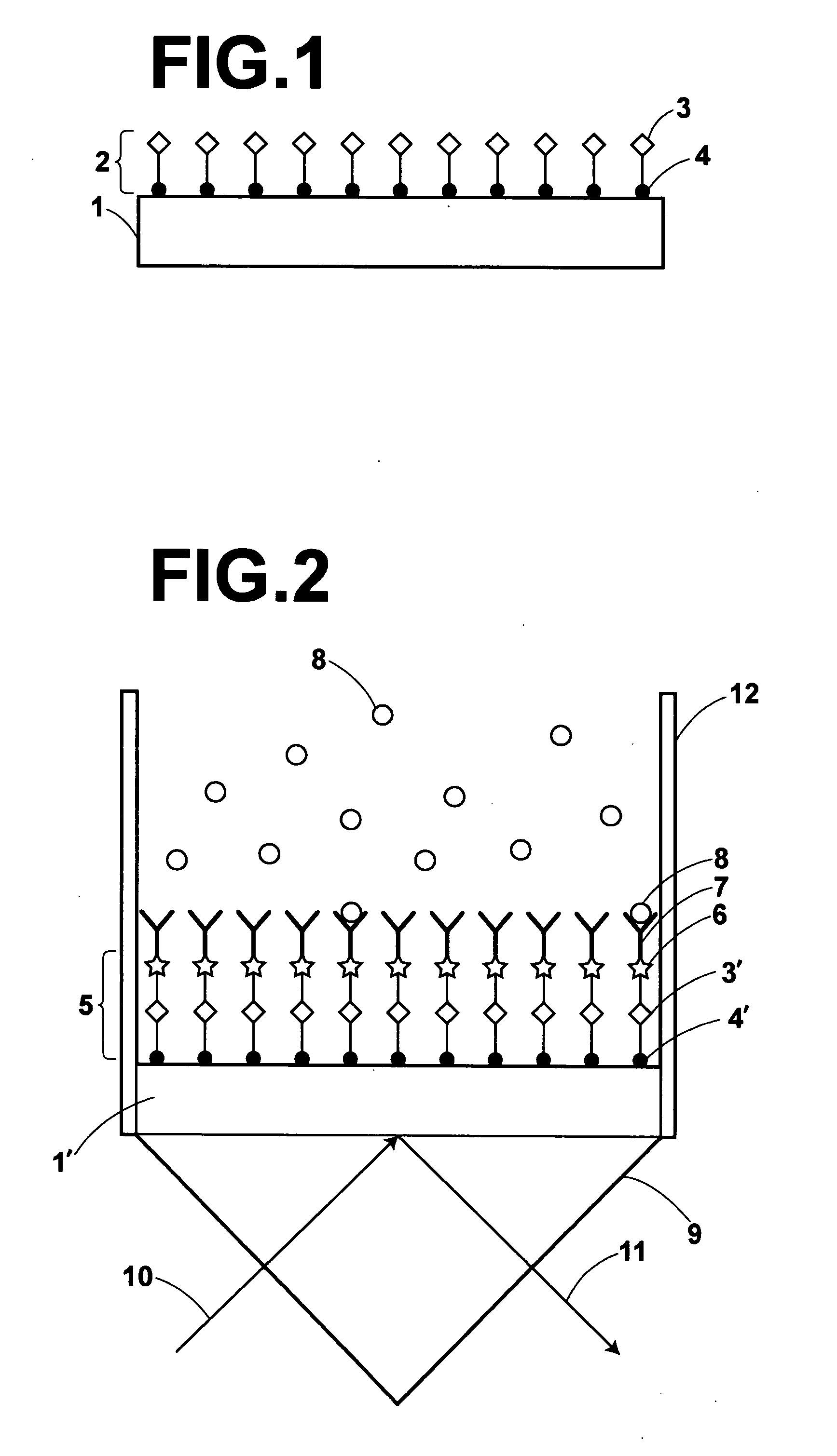
[0007] An object of the present invention is to provide an optical device being arranged for use with a sensor, having a structure which can excite plasmon resonance such as surface plasmon resonance or localized plasmon resonance, and exhibiting high performance and high durability, by forming a film of a material capable of preventing oxidation of a metallic layer without degradation of the performance of the optical device.
[0008] Another object of the present invention is to provide a surface-plasmon-resonance biosensor having a measurement chip which contains a metallic layer, and exhibiting high performance and high durability, by forming a film of a material capable of preventing oxidation of the metallic layer without degradation of the performance of the surface-plasmon-resonance biosensor.
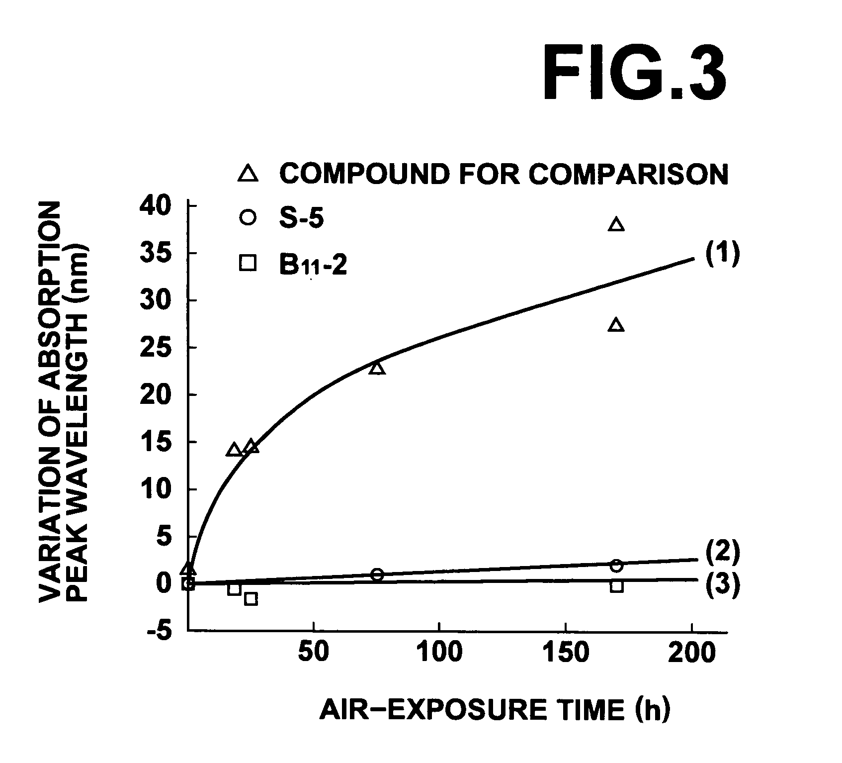
[0011] In addition, since the compound contains a benzene ring or a hetero ring, the benzene ring or the hetero ring blocks out the air. Further, when the compound is a reductive compound, oxygen existing around the surface of the optical device is reduced, and therefore the metal film is not exposed to oxygen. Thus, it is possible to effectively prevent oxidation of the metal film and deterioration of the characteristics of the optical device.

Problems solved by technology

It is known that the above sensors use devices having a metallic layer (such as a metal film or a layer on which minute metal particles are arrayed), and the characteristics of each device deteriorate due to oxidation of the metallic layer.
However, since the above devices are provided for sensors each of which detects a change occurring in a material absorbed by a surface of the metallic layer, there is a possibility that the functions of the device for use with a sensor is impaired by formation of an antioxidant film on the metallic layer.
However, it is known that formation of such a thin film as not to impair the essential functions of a device for use with a sensor is not easy, and the sensitivity of a sensor is decreased by the provision of the thin film.

Method used


Image

  • Optical device utilizing plasmon resonance
  • Optical device utilizing plasmon resonance
  • Optical device utilizing plasmon resonance

Examples


Embodiment Construction

[0018] Embodiments of the present invention are explained in detail below with reference to the drawings.

Optical Devices

[0019] The present invention is applicable to any optical devices having a structure which enables excitation of surface plasmon resonance or localized plasmon resonance. Therefore, hereinbelow, some examples of structures which are known to enable excitation of surface plasmon resonance or localized plasmon resonance are indicated.

[0020] U.S. Pat. No. 5,917,607 and Japanese Unexamined Patent Publications Nos. 2002-357537 and 11(1999)-223597 disclose surface-plasmon-resonance sensors in which surface plasmon resonance is excited by using different structures.

[0021] In the structure for excitation of surface plasmon resonance disclosed in U.S. Pat. No. 5,917,607, a metal film is formed on a prism. In a known structure similar to the structure disclosed in JPP 09-292332, a dielectric layer or an air layer is arranged between a prism and a metal film. In another ...


PUM

PropertyMeasurementUnit
refractive indexaaaaaaaaaa
dielectric constantaaaaaaaaaa

Abstract

An optical device having a structure which contains a metallic layer and enables excitation of plasmon resonance, such as a measurement chip for use with a surface-plasmon-resonance biosensor having a metallic layer. In order to prevent oxidation of the metallic layer, the metallic layer is covered with a film made of a mercapto compound containing a benzene ring and / or a hetero ring, or a reductive compound containing a metal-binding group which can be bound to the metal of which the metallic layer is made.

Description

BACKGROUND OF THE INVENTION [0001] 1. Field of the Invention [0002] The present invention relates to an optical device which utilizes a phenomenon related to plasmon resonance, for example, surface plasmon resonance or localized plasmon resonance. Such an optical device includes a measurement chip being arranged for use with a sensor and having a structure which can excite surface plasmon resonance or localized plasmon resonance. The present invention also relates to a surface-plasmon-resonance biosensor including a measurement chip having a structure which can excite surface plasmon resonance or localized plasmon resonance. [0003] 2. Description of the Related Art [0004] In the fields of biochemistry and medical inspection, identification and analysis of materials are performed by utilizing surface plasmon resonance. U.S. Pat. No. 5,917,607 discloses sensors being used in such identification or analysis and each having a structure in which a metal film is formed on a face of prism ...

Claims


Application Information

Patent Timeline
Patent Type & Authority Applications(United States)
IPC IPC(8): C07C259/06G01N33/543C07C335/20C07D409/12C12Q1/68C23C26/00G01N21/27G01N21/41G01N33/53
CPCG01N21/554G01N21/553
Inventor NAYA, MASAYUKISASAKI, HIROTOMOINABA, TADASHIEZOE, TOSHIHIDE
Owner FUJIFILM HLDG CORP
Learn More