Semiconductor device with alternating conductivity type layer and method of manufacturing the same
a semiconductor layer and alternating conductivity technology, applied in the field of vertical semiconductor structure, can solve the problems of high breakdown voltage of mosfet, difficult to bury a good quality semiconductor layer in such a narrow and deep trench, and difficult to employ selective etching technique for digging trenches, etc., to achieve low electrical resistance and easy manufacturing
- Summary
- Abstract
- Description
- Claims
- Application Information
AI Technical Summary
Benefits of technology
Problems solved by technology
Method used
Image
Examples
first embodiment
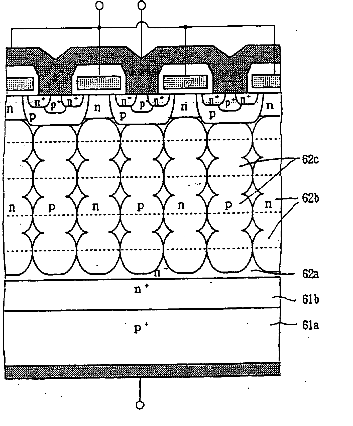
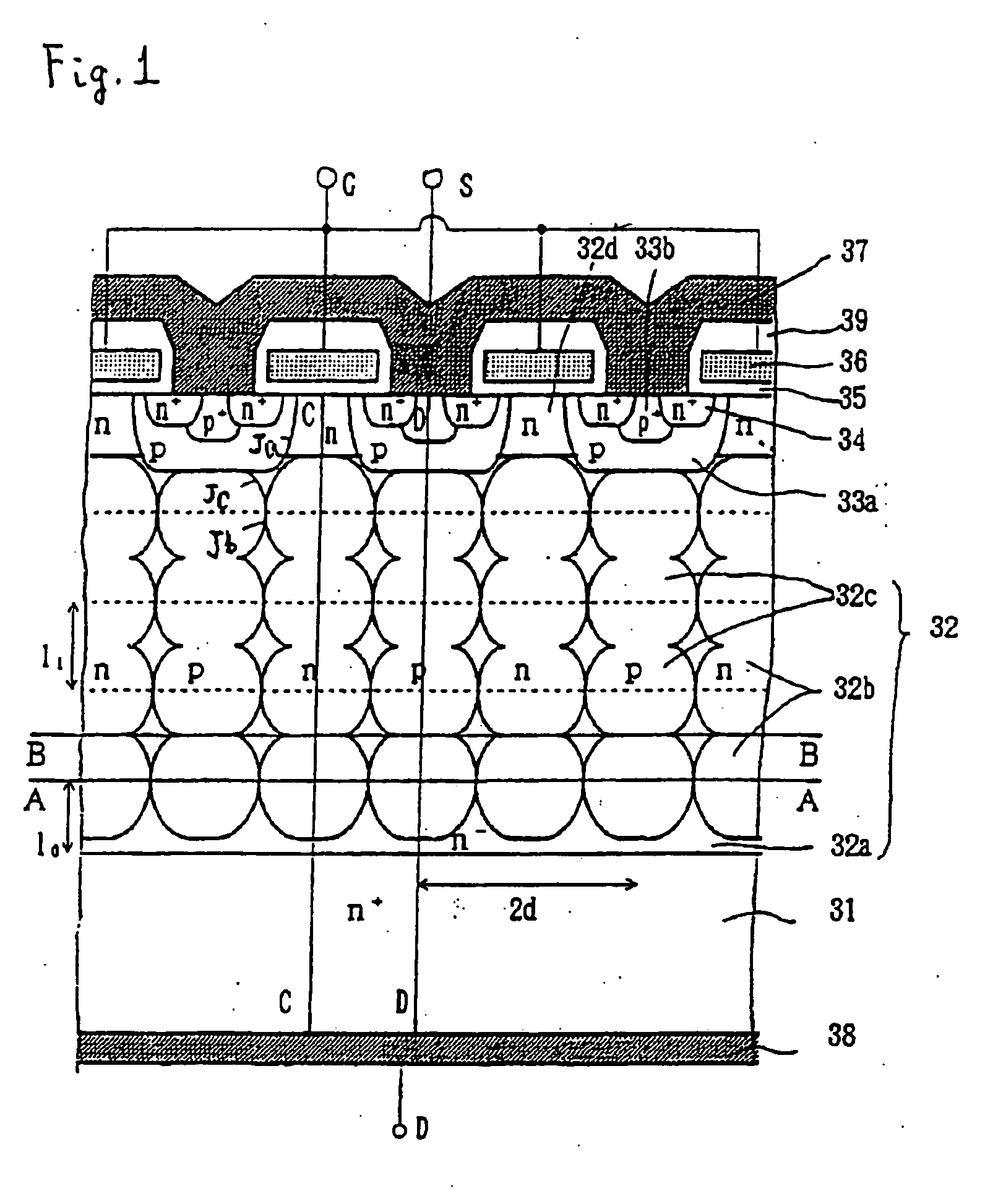
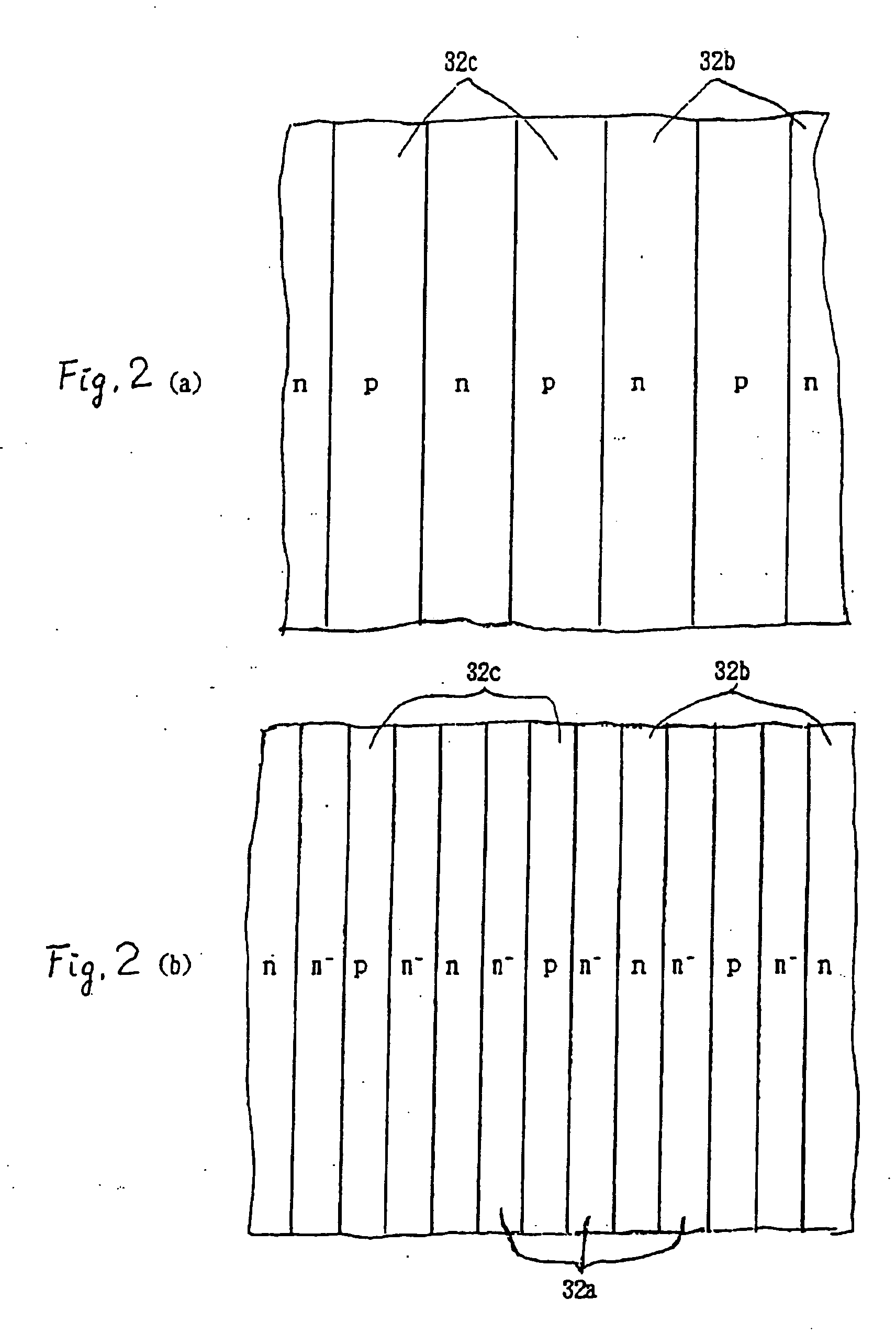
[0053]FIG. 1 is a cross section of a semiconductor device with an alternating conductivity type layer according to a first embodiment of the invention. FIG. 2(a) is a cross section along A-A of the semiconductor device with an alternating conductivity type layer of FIG. 1. FIG. 2(b) is a cross section along B-B of the semiconductor device with an alternating conductivity type layer of FIG. 1.
[0054] Referring now to FIG. 1, a semiconductive substrate region 32 is formed on an n+-type, low resistance, drain layer 31. Semiconductive substrate region 32 includes a highly resistive n−-type layer 32a, a plurality of vertical alignments of n-type buried regions 32b and a plurality of vertical alignments of p-type buried regions 32c. The vertical alignments of n-type buried regions 32b and the vertical alignments of p-type buried regions 32c are alternately arranged with each other horizontally. An n-type channel layer 32d is in contact with the uppermost n-type buried region 32b. A p-type...
second embodiment
[0081]FIG. 13 is a cross section of a semiconductor device with alternating conductivity type layer according to a second embodiment of the invention.
[0082] Referring now to FIG. 13, a drift layer 42 is on an n+-type drain layer 41 with low resistance. Drift layer 42 includes a highly resistive layer 42a, a plurality of vertical alignments of n-type buried regions 42b and a plurality of vertical alignments of p-type buried regions 42c. The vertical alignments of n-type buried regions 42b and the vertical alignments of p-type buried regions 42c are alternately arranged with each other horizontally. In the surface portion of drift layer 42, n-type channel layers 42d are formed on the uppermost n-type buried regions 42b and p-type base regions 43a on the uppermost p-type buried regions 42c. An n+-type source region 44 and a heavily doped p+-type well region 43b are in p-type base region 43a. A gate electrode layer 46 is above the extended portion of p-type base region 43a extended bet...
third embodiment
[0087]FIG. 14 is a cross section of a semiconductor device with an alternating conductivity type layer according to a third embodiment of the invention.
[0088] The semiconductor device shown in FIG. 14 is a UMOSFET that includes trench gates. The gate structure of the UMOSFET is different from that of the MOSFET according to the first embodiment. Referring now to FIG. 14, trenches are dug in the surface portion of a drift layer 52. A gate electrode layer 56 is surrounded by a gate insulation film 55 in the trench. In the remaining surface portion of drift layer 52, p-type base layers 53a are formed in the depth as shallow as that of gate electrode layer 56, and n+ source regions 54 are formed along the upper edges of gate electrode layers 56. A thick insulation film 59 covers gate electrode layers 56. Drift layer 52 includes a plurality of vertical alignments of n-type buried regions 52b and a plurality of vertical alignments of p-type buried regions 52c, in a similar manner as in t...
PUM
 Abstract
Description
Claims
Application Information
 - R&D
- Intellectual Property
- Life Sciences
- Materials
- Tech Scout
- Unparalleled Data Quality
- Higher Quality Content
- 60% Fewer Hallucinations
Browse by: Latest US Patents, China's latest patents, Technical Efficacy Thesaurus, Application Domain, Technology Topic, Popular Technical Reports.
© 2025 PatSnap. All rights reserved.Legal|Privacy policy|Modern Slavery Act Transparency Statement|Sitemap|About US| Contact US: help@patsnap.com


