Coating solutions for use in forming bismuth-based ferroelectric thin films and a method of forming bismuth-based ferroelectric thin films using the coating solutions

a technology of coating solutions and ferroelectric thin films, which is applied in the direction of liquid/solution decomposition chemical coating, lignin derivatives, organic chemistry, etc., can solve the problems of increasing the chance of thermal damage to ic circuits and substrates, and not being suitable for practical applications, and achieves rapid conversion and small weight loss

Inactive Publication Date: 2005-07-21
SATO YOSHIMI +2
View PDF6 Cites 4 Cited by
  • Summary
  • Abstract
  • Description
  • Claims
  • Application Information

AI Technical Summary

Benefits of technology

[0010] An object, therefore, of the present invention is to provide a coating solution for use in forming Bi-based ferroelectric thin films that may include one or more of the advantages of permitting organic components to be decomposed at low enough temperature, forming a coat that permits rapid conversion to inorganic nature, and forming a coat that loses only small weight after decomposition of organic components.

Problems solved by technology

However, due to the great number of oxide components of metallic elements that have to be incorporated as film constituents, sputtering and CVD techniques require costly apparatus, and considerable difficulties are involved in controlling the compositions of ferroelectric thin films at desired levels; hence, these techniques are not suitable for practical applications, particularly on large-diameter substrates.
However, the prolonged heat treatment at elevated temperature has the disadvantage of increasing the chance of causing thermal damage to IC circuits and substrates.

Method used


Image

  • Coating solutions for use in forming bismuth-based ferroelectric thin films and a method of forming bismuth-based ferroelectric thin films using the coating solutions
  • Coating solutions for use in forming bismuth-based ferroelectric thin films and a method of forming bismuth-based ferroelectric thin films using the coating solutions
  • Coating solutions for use in forming bismuth-based ferroelectric thin films and a method of forming bismuth-based ferroelectric thin films using the coating solutions

Examples


example 1

Evaluation of TG Curves

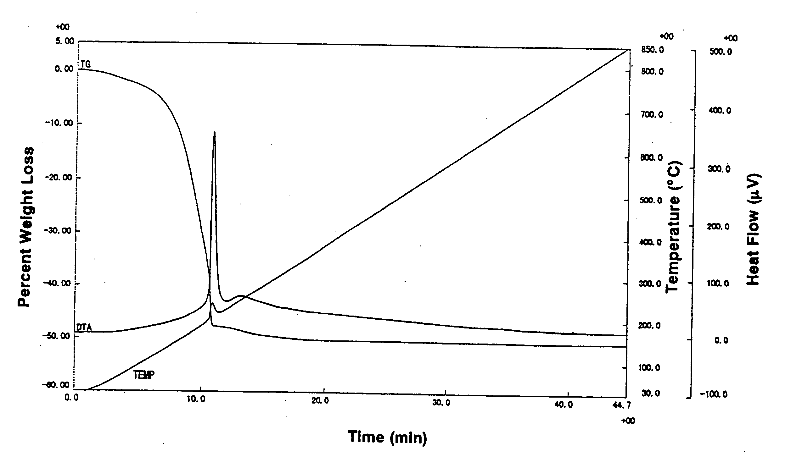
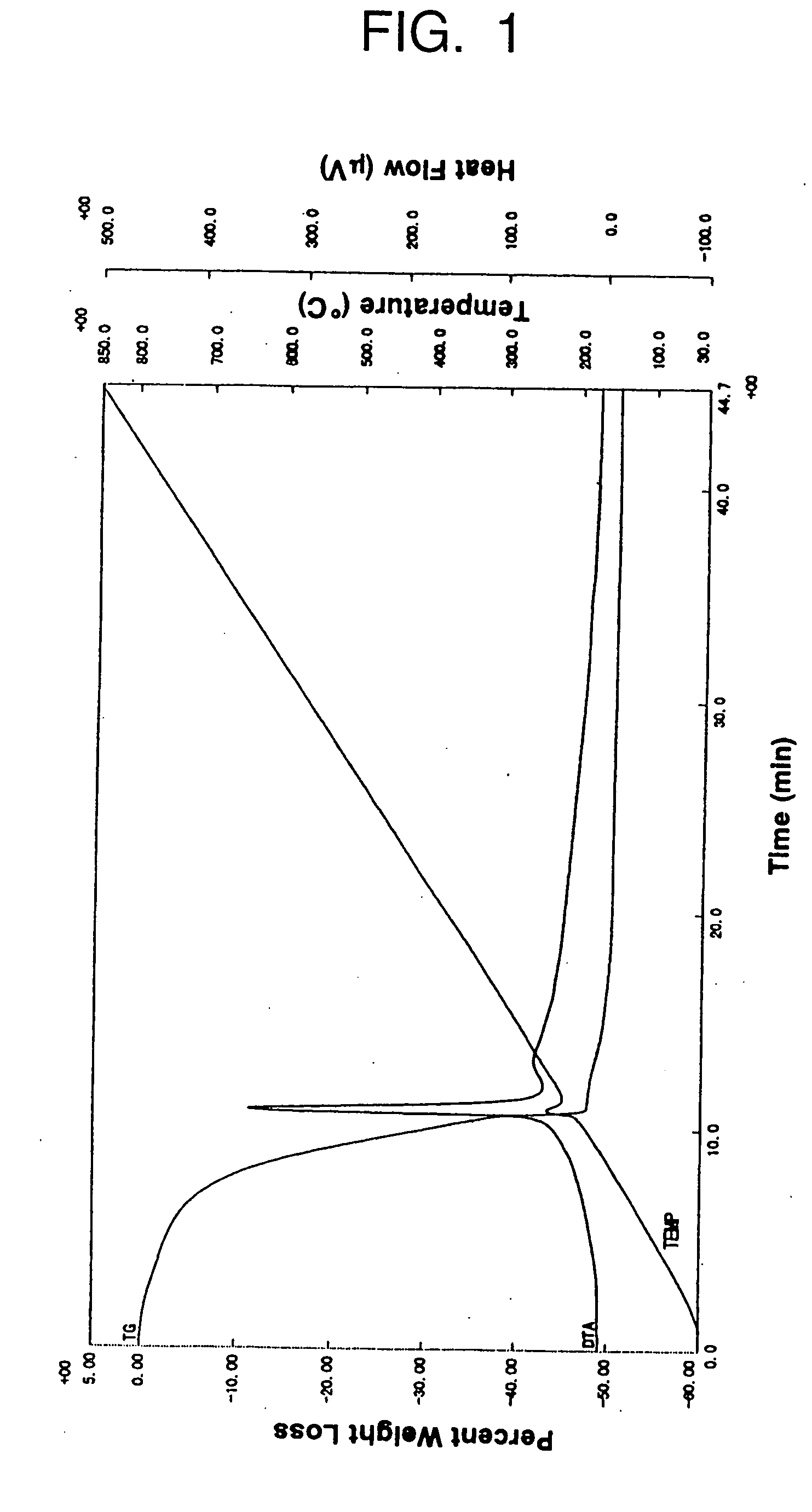
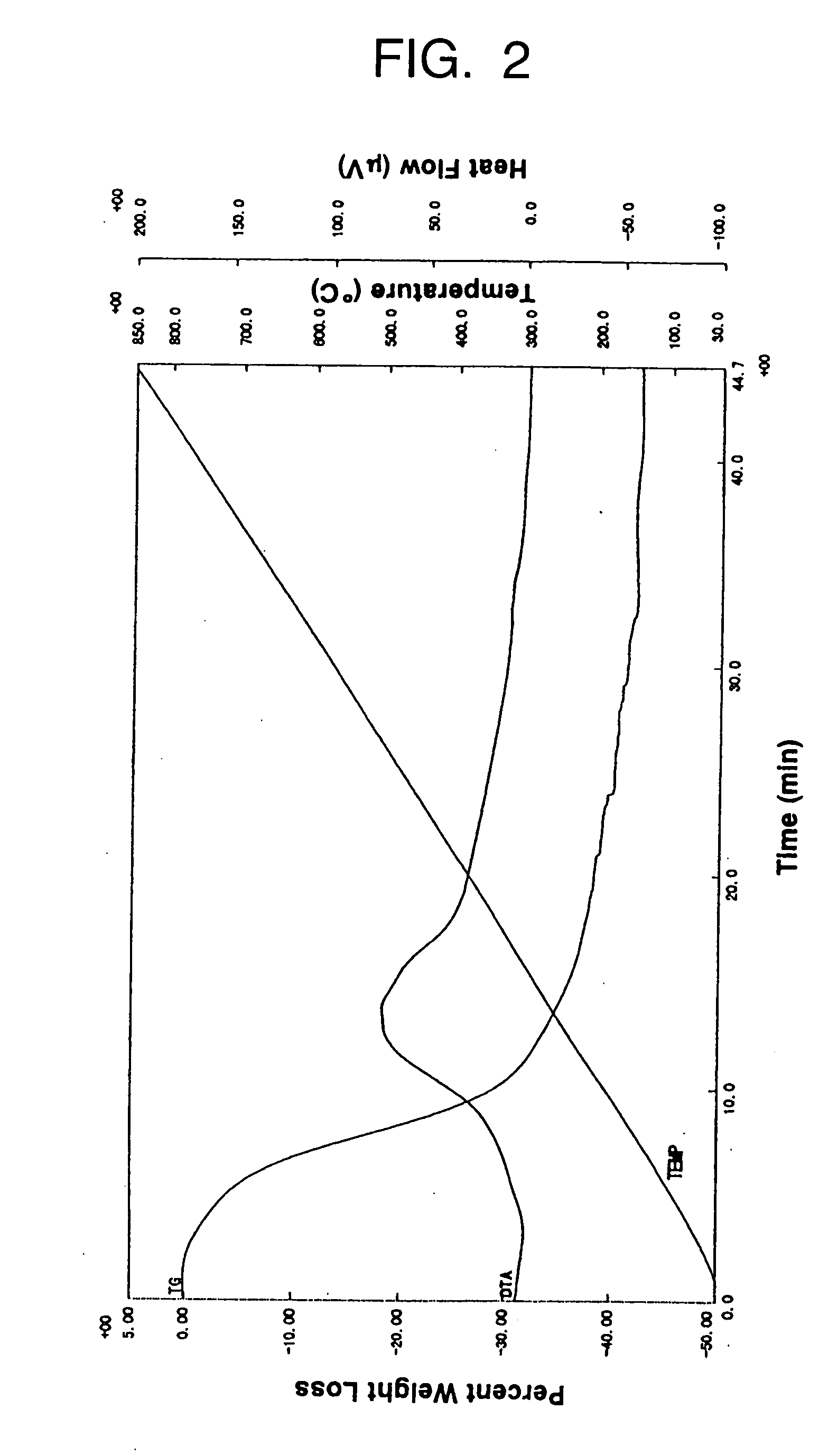
[0142] The coating solutions prepared in Syntheses 1-11 and Comparative Syntheses 1-6 were heated at a rate of 20° C. / min to remove the solvent; after cooling down to 20° C., the coating solutions were again heated at a rate of 20° C. / min to determine TG (thermogravimetric) curves. The TG curves for coating solutions 1-11 are shown in FIGS. 1-11 and those for comparative coating solutions 1-6 are shown in FIGS. 12-17. In FIGS. 1-17, curves labelled TEMP show the temperature (° C.) of the as-applied coat.

[0143] By comparing FIGS. 1-11 with FIGS. 12-17, one can see that coating solutions 1-11 had low enough decomposition temperatures for the organic components that they were converted to inorganic nature within short periods whereas they lost weight by only about 25-45% after decomposition of the organic components. It is clear from FIG. 13 that comparative coating solution 2 using 2-ethylhexanoic acid suffered a significant weight loss of about 60%.

example 2

Evaluation of XRD Analyses

[0144] The coating solutions prepared in Syntheses 1-3, 5 and 9 were whirl coated on silicon wafers with a spinner and dried at 80° C. for 3 minutes to form dry coats 60 nm thick. The same procedure was further repeated twice to form dry coats 180 nm thick.

[0145] The coatings were heated up to 700° C. at a rate of 100° C. / s and heat treated at the same temperature for 1 minute to form Bi-based ferroelectric thin films. The XRD curves for coating solutions 1-3, 5 and 9 are shown in FIGS. 18-22, respectively, and the XRD curve for comparative coating solution 1 is shown in FIG. 23.

[0146] Judging from the peak intensities for 2θ values of about 29°, 33° and 48° in FIGS. 18-23, the ferroelectric films formed from coating solutions 1-3, 5 and 9 had good crystallinity in the substantial absence of the fluorite structure whereas the ferroelectric film formed from comparative coating solution 1 had only poor crystallinity since it partly included the fluorite st...

example 3

Evaluation of Film Quality by SEM

[0147] The coating solutions prepared in Synthesis 1 and Comparative Synthesis 1 were whirl coated on silicon wafers with a spinner and dried at 50° C. for 5 minutes, then heated at 500° C. for 30 minutes to form dry coats 60 nm thick.

[0148] The same procedure was further repeated twice, and then a heat treatment was performed at 750° C. for 60 minutes to form Bi-based ferroelectric thin films 180 nm thick.

[0149] A SEM of the ferroelectric thin film formed from coating solution 1 is shown in FIG. 24, and a SEM of the ferroelectric thin film formed from comparative coating solution 1 is shown in FIG. 25. As is clear from comparison between FIGS. 24 and 25, the ferroelectric thin film formed from coating solution 1 had high quality since it consisted of fine crystal grains that produced a dense structure with a limited number of voids.


PUM

PropertyMeasurementUnit
temperatureaaaaaaaaaa

Abstract

Disclosed herein is a coating solution for use in forming Bi-based ferroelectric thin films comprises a specified compound, such as triglyme, dipivaloylmethane, pinacol, pivalic acid or hexyleneglycol, in combination with an organometallic compound containing metallic elements of which a Bi-based ferroelectric thin film to be formed is composed. Disclosed also herein is a method of forming Bi-based ferroelectric thin films using the coating solution.

Description

BACKGROUND OF THE INVENTION [0001] 1. Field of the Invention [0002] This invention relates to coating solutions for use in forming Bi-based ferroelectric thin films and a method of forming bis-muth-based ferroelectric thin films using such coating solutions. The invention is particularly suitable for application to non-volatile ferroelectric memories and the like. [0003] 2. Description of Related Art [0004] Thin films of bismuth layer-structured ferroelectrics (BLSF) represented by the general formula (Bi2O2)2+(Am−1BmO3m+1)2− [where A is a mono-, di- or trivalent ion (as of Bi, Pb, Ba, Sr, Ca, Na, K or a rare earth element) or combinations of these ions; B is a tetra-, penta- or hexavalent ion (as of a metallic element like Ti, Nb, Ta, W, Mo, Fe, Co or Cr) or combinations of these ions; and m is an integer of 1-5] have recently been found to feature good characteristics such as requiring small remanent polarization(Pr)-coercive field(Ec) hysteresis curves, i.e., P-E hysteresis curve...

Claims


Application Information

Patent Timeline
Patent Type & Authority Applications(United States)
IPC IPC(8): C23C18/12H01L21/28H01B3/00H01L21/314H01L21/316
CPCC23C18/1216H01L21/31691H01L21/28291C23C18/1283H01L29/40111H01L21/02197H01L21/02282H01B3/00
Inventor SATO, YOSHIMIKAWAKAMI, ATSUSHITAKEUCHI, YOSHIYUKI
Owner SATO YOSHIMI
Why Eureka
Try Eureka