

Radiation-sensitive resin composition
a technology of resin composition and radiation, applied in the direction of photosensitive materials, other chemical processes, instruments, etc., can solve the problems of reducing dimensional accuracy, insufficient resolution capability alone, and difficulty in producing such a minute pattern at high precision
Inactive Publication Date: 2005-07-21
JSR CORPORATIOON
View PDF17 Cites 12 Cited by
- Summary
- Abstract
- Description
- Claims
- Application Information
AI Technical Summary
Benefits of technology
The composition achieves excellent resolution performance and minimizes nano-edge roughness, making it suitable for the fabrication of increasingly smaller semiconductor devices with improved dimensional accuracy and electric performance.
Problems solved by technology
However, it is difficult to produce such a minute pattern at high precision by conventional methods using visible light (wavelength: 800-400 nm) or near ultraviolet light (wavelength: 400-300 nm).
However, when a stringent line-width control is required such as in the case of fabricating devices with sub-half micron or less dimensions, resolution capability alone is insufficient.
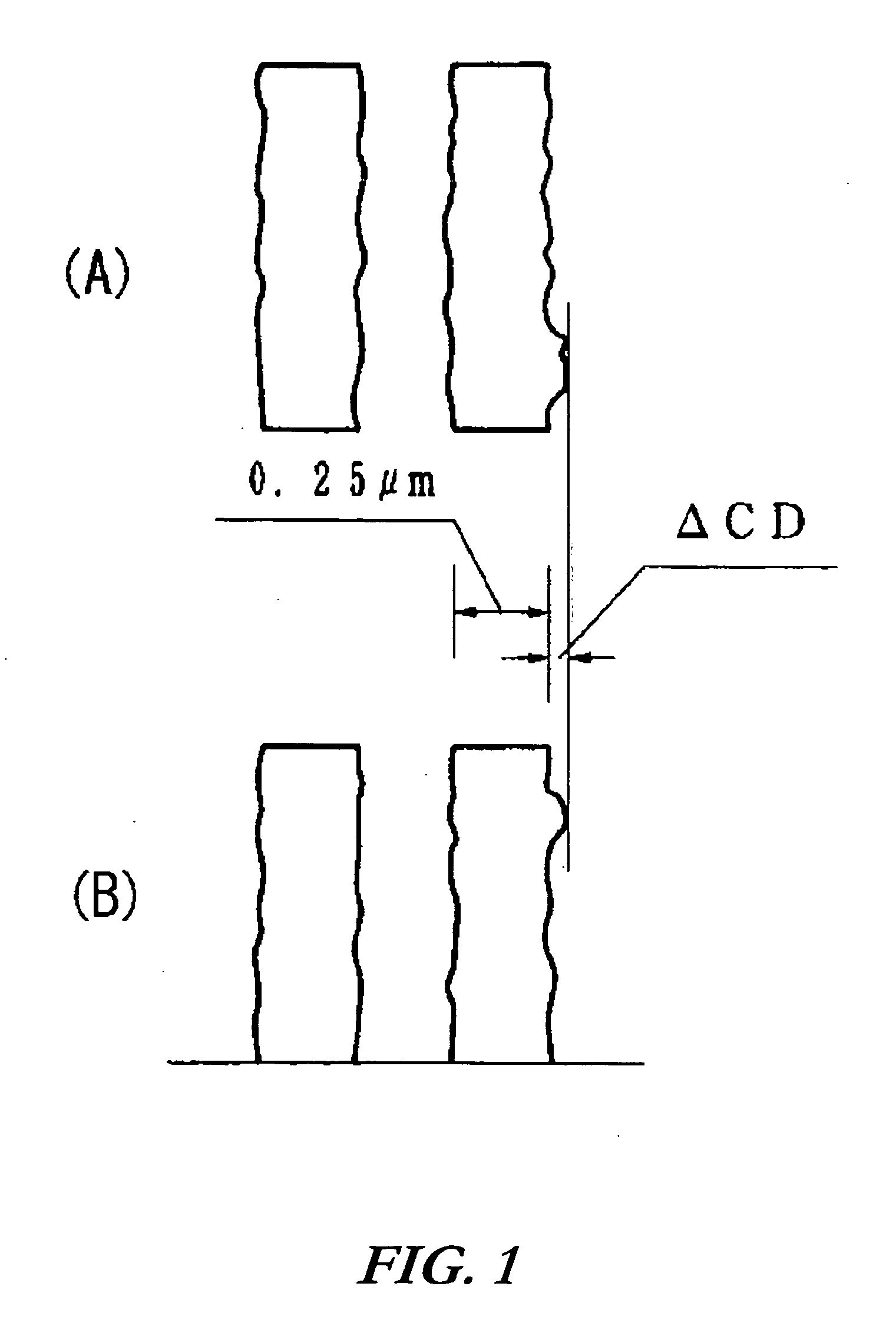
If a chemically amplified resist exhibiting poor film surface smoothness is used, irregularities (such as nano edge roughness) on the film-surface is transferred to a substrate when a resist pattern is transferred to the substrate by an etching process or the like, giving rise to a decrease in dimensional accuracy and impaired electric performance in the ultimate devices (see, for example, J. Photopolym. Sci. Tech.
Method used
View moreImage
Smart ImageViewing Examples

Examples
examples
[0683] The embodiments of the present invention will be described in more detail by examples. However, these examples should not be construed as limiting the present invention.
Login to View More PUM
| Property | Measurement | Unit |
|---|---|---|
| line-width precision | aaaaa | aaaaa |
| line-width | aaaaa | aaaaa |
| wavelength | aaaaa | aaaaa |
Abstract
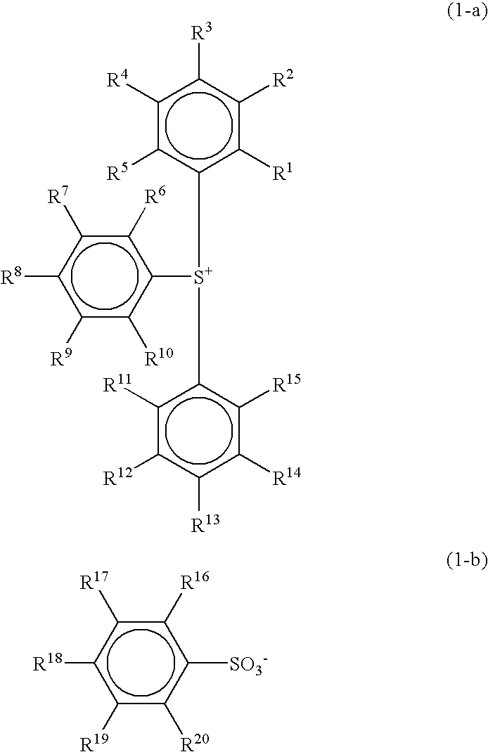
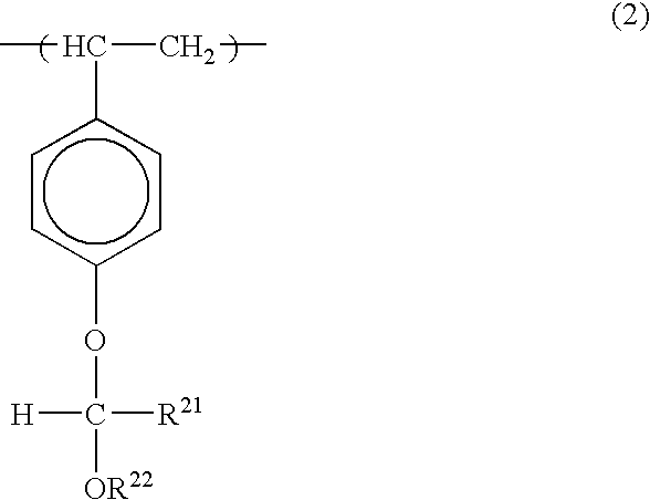
A radiation-sensitive resin composition comprising (A) a photoacid generator such as 2,4,6-trimethylphenyldiphenylsulfonium 2,4-difluorobenzenesulfonate or 2,4,6-trimethylphenyldiphenylsulfonium 4-trifluoromethylbenzenesulfonate and (B) a resin having an acetal structure typified by a poly(p-hydroxystyrene) resin in which a part of hydrogen atoms of phenolic hydroxyl groups have been replaced by 1-ethoxyethyl groups, 1-ethoxyethyl groups and t-butoxycarbonyl groups, or 1-ethoxyethyl groups and t-butyl groups. The resin composition is sensitive to deep ultraviolet rays and charged particles such as electron beams, exhibits excellent resolution performance and pattern shape-forming capability, and suppresses a nano-edge roughness phenomenon to a minimal extent.
Description
BACKGROUND OF THE INVENTION [0001] 1. Field of the Invention [0002] The present invention relates to a radiation-sensitive resin composition useful as a chemically amplified resist for microfabrication using various radiations, in particular, deep ultraviolet rays such as a KrF excimer laser and ArF excimer laser, charged particle rays such as electron beams, and X-rays. [0003] 2. Description of the Background Art [0004] In the field of microfabrication exemplified by the manufacture of an integrated circuit device, development of a lithographic process capable of reproducing microfabrication with a line-width precision of 0.5 μm or less has been pursued in recent years to achieve higher integration. To ensure microfabrication in the order of 0.5 μm or less, a resist which can excellently reproduce patterns with a 0.5 μm or less line-width has been required. However, it is difficult to produce such a minute pattern at high precision by conventional methods using visible light (wavel...
Claims
Login to View More Application Information
Patent Timeline
 Patent Type & AuthorityApplications(United States)
IPC IPC(8): C08K5/375C08K5/42C08L25/18C09K3/00G03F7/004G03F7/039H01L21/027
CPCG03F7/0045G03F7/0392Y10S430/122Y10S430/118Y10S430/114Y10S430/115Y10S430/106G03F7/004
InventorSUZUKI, AKIMURATAHARA, HIROMICHIKOBAYASHI, EIICHI
OwnerJSR CORPORATIOON