Double-side polishing method and apparatus

a single-carrying, polishing technology, applied in the direction of cutting machines, manufacturing tools, edge grinding machines, etc., can solve the problems of difficult to secure mechanical precision or suppress apparatus costs, difficult to secure flatness of wafers from polishing principles, and difficulty in enhancing flatness of work. , to achieve the effect of enhancing flatness of work

Active Publication Date: 2005-07-21
KASHIWARA KIKAI SEISAKUSHIYO +1
View PDF5 Cites 13 Cited by
  • Summary
  • Abstract
  • Description
  • Claims
  • Application Information

AI Technical Summary

Benefits of technology

[0024] In double-side polishing method and apparatus of the present invention, a carrier larger in diameter than upper and lower surface plates that rotate is inserted between the surface plates and, when a work held in the carrier is polished on both surfaces thereof by rotation of the upper and lower surface plates, t

Problems solved by technology

In a case where such a large diameter wafer is polished on both surfaces thereof, a scale will be tremendously larger in a multicarrier type double-side polishing apparatus using plural carriers as in the case of the planetary gear mechanism type, leading to much of difficulty in securing a mechanical precision or suppressing an apparatus cost.
Conventional single wafer type double-side polishing apparatuses including the apparatus provided in JP-A 2001-315057, however, have an intrinsic problem that a flatness of a wafer is harder to be secured from a polishing principle, as compared with a multicarrier type double-side polishing apparatus using plural carriers as in the case of the planetary gear type.
As a result, a polishing rate at a point on the wafer by the surface plates is greatly different between the central portion and the outer peripheral portion of the wafer and no change occu

Method used


Image

  • Double-side polishing method and apparatus
  • Double-side polishing method and apparatus
  • Double-side polishing method and apparatus

Examples


example

[0050] Then, there is shown an example of the present invention in which a silicon wafer is polished simultaneously on both sides thereof according to the present invention and by comparison with a conventional example, the effect of the present invention will be made clear.

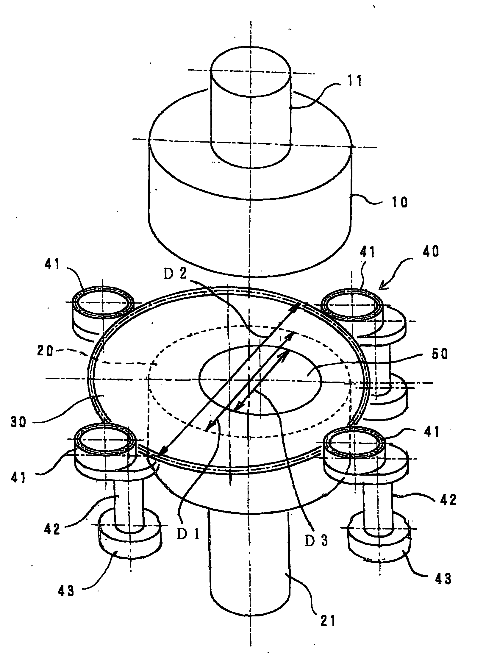
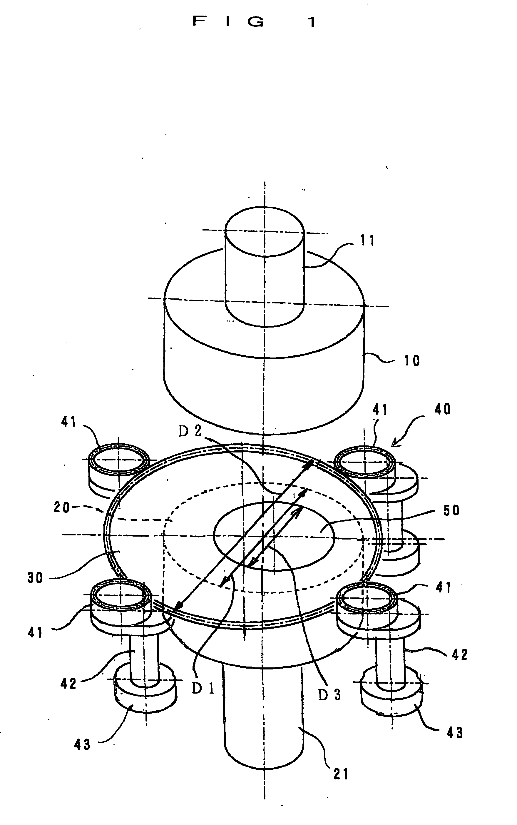
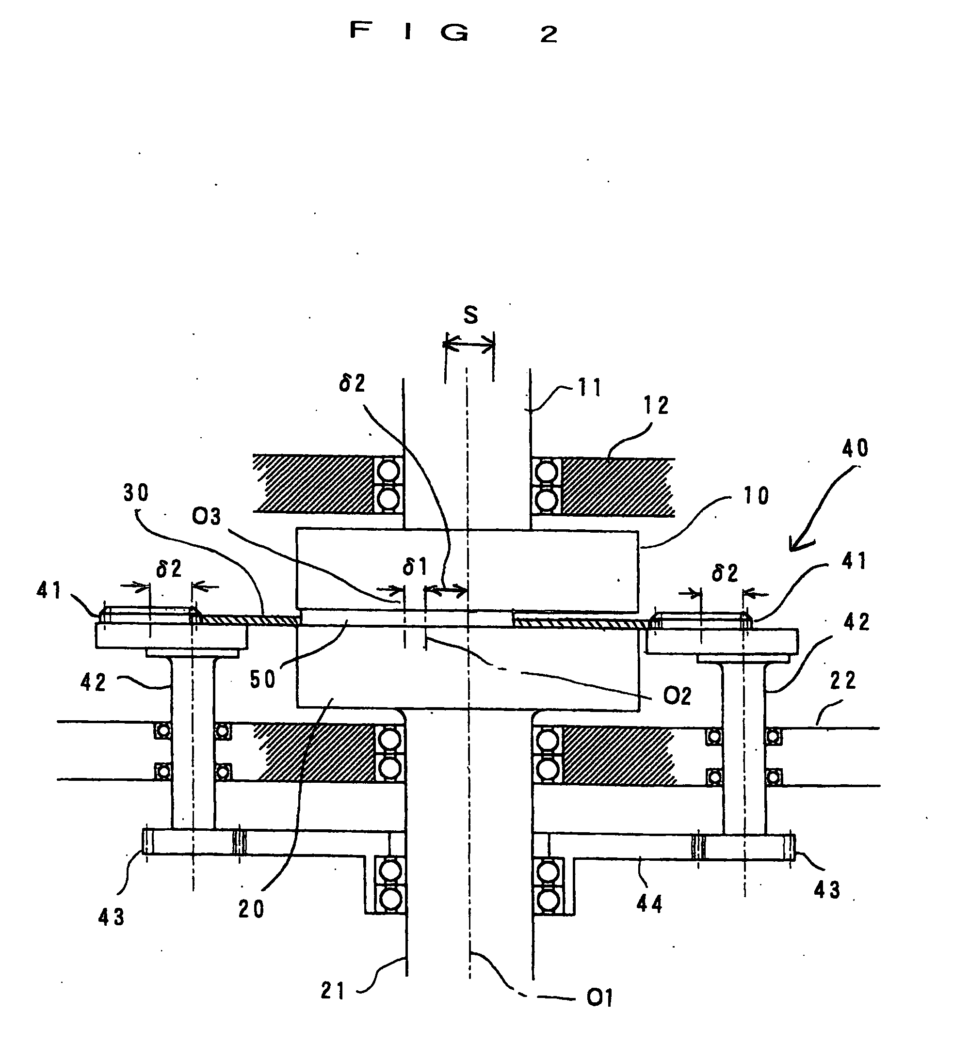
[0051] The double-side polishing apparatus (with a diameter of each of the surface plates of 380 mm) shown in FIGS. 1 to 3 was used and a 300 mm silicon wafer of 0.8 mm in thickness was polished on both sides thereof using the following members or materials, which were used in a general primary polishing stage of a silicon wafer.

[0052] A carrier to be used: a resin carrier (outer diameter: 510 mm, thickness: 0.7 mm).

[0053] A polishing pad: a polishing cloth SUBA800 manufactured by Rodel Nitta Company.

[0054] A polishing liquid: a 20-fold diluted slurry of Nalco 2350.

[0055] Polishing conditions were as follows. The upper and lower surface plates were rotated in opposed directions at a speed of 20 rpm in order ...


PUM

PropertyMeasurementUnit
Diameteraaaaaaaaaa

Abstract

In order to improve a flatness of a work in single wafer type double-side polishing in which one wafer is polished with one carrier, a carrier larger in diameter than upper and lower surface plates that rotate is inserted between the surface plates, and a wafer smaller in diameter than the surface plates is held with the carrier. The carrier is rotated by plural eccentric gears that mesh with external gear teeth formed on the outer peripheral surface of the carrier at plural positions along a circumferential direction thereof and revolve around positions spaced from the centers as centers in synchronism with each other or one another at the plural positions of meshing. The carrier rotates about its center and moves circularly around the center of the surface plates spaced from the center thereof. The upper surface plate is reciprocated in a direction perpendicular to the central axis when required. Geometrical motion loci of points on the wafer are complex and peripheral speeds alter to large extents to thereby enhance equalization of peripheral speeds of points on the wafer to a higher level to thereby improve a flatness.

Description

BACKGROUND OF THE INVENTION [0001] 1. Field of the Invention [0002] The present invention relates to single carrier type double-side polishing method and apparatus suitable for both-surface polishing of a semiconductor wafer, which is a raw material for a semiconductor device, and more particularly, to double-side polishing method and apparatus suitable for single wafer type polishing which processes one wafer with one carrier. [0003] 2. Description of the Related Art [0004] As for double-side polishing of a semiconductor wafer, which is a raw material for a semiconductor device, there has been well used a planetary gear mechanism type double-side polishing apparatus. A planetary gear mechanism type double-side polishing apparatus is a kind of a batch type apparatus simultaneously polishing both surfaces of each of plural wafers. In a planetary gear mechanism type double-side polishing apparatus, plural carriers are inserted between rotatable upper and lower surface plates. The plur...

Claims


Application Information

Patent Timeline
IPC IPC(8): B24B37/08B24B37/27B24B37/28H01L21/304
CPCB24B37/28B24B37/08H01L21/304
Inventor HORIGUCHI, AKIRANAKAO, SHOJI
Owner KASHIWARA KIKAI SEISAKUSHIYO
Why Eureka
Try Eureka