Method of fabricating diffractive lens array and UV dispenser used therein

a technology of diffractive lenses and molds, applied in the field of fabricating diffractive lens array molds and ultraviolet (uv) dispensers, can solve the problems of geometric error, inability to fabricate doe arrays with patterned microstructures, and less accuracy in fabricating, and achieve excellent productivity and eliminate alignment errors

Inactive Publication Date: 2005-07-28
SAMSUNG ELECTRONICS CO LTD
View PDF3 Cites 45 Cited by
  • Summary
  • Abstract
  • Description
  • Claims
  • Application Information

AI Technical Summary

Benefits of technology

[0012] It is therefore an object of the present invention to provide a method of fabricating a diffractive lens array that eliminates alignment erro

Problems solved by technology

However, due to less accuracy in fabricating micropatterns and the difficulty in fabricating asymmetric complex patterns, lithography is more prevalently used in fabrication of DOEs on which microstructures have been patterned than direct machining.
However, expensive EBL equipment and long processing times make it impossible to fabricate a DOE array with patterned microstructures.
Replication by Ni electroplating shows almost perfect transferability but suffers from a geometric

Method used


Image

  • Method of fabricating diffractive lens array and UV dispenser used therein
  • Method of fabricating diffractive lens array and UV dispenser used therein
  • Method of fabricating diffractive lens array and UV dispenser used therein

Examples


Embodiment Construction

[0025] The present invention is now described in further detail by reference to the drawings. However, the present invention should not be construed as being limited thereto.

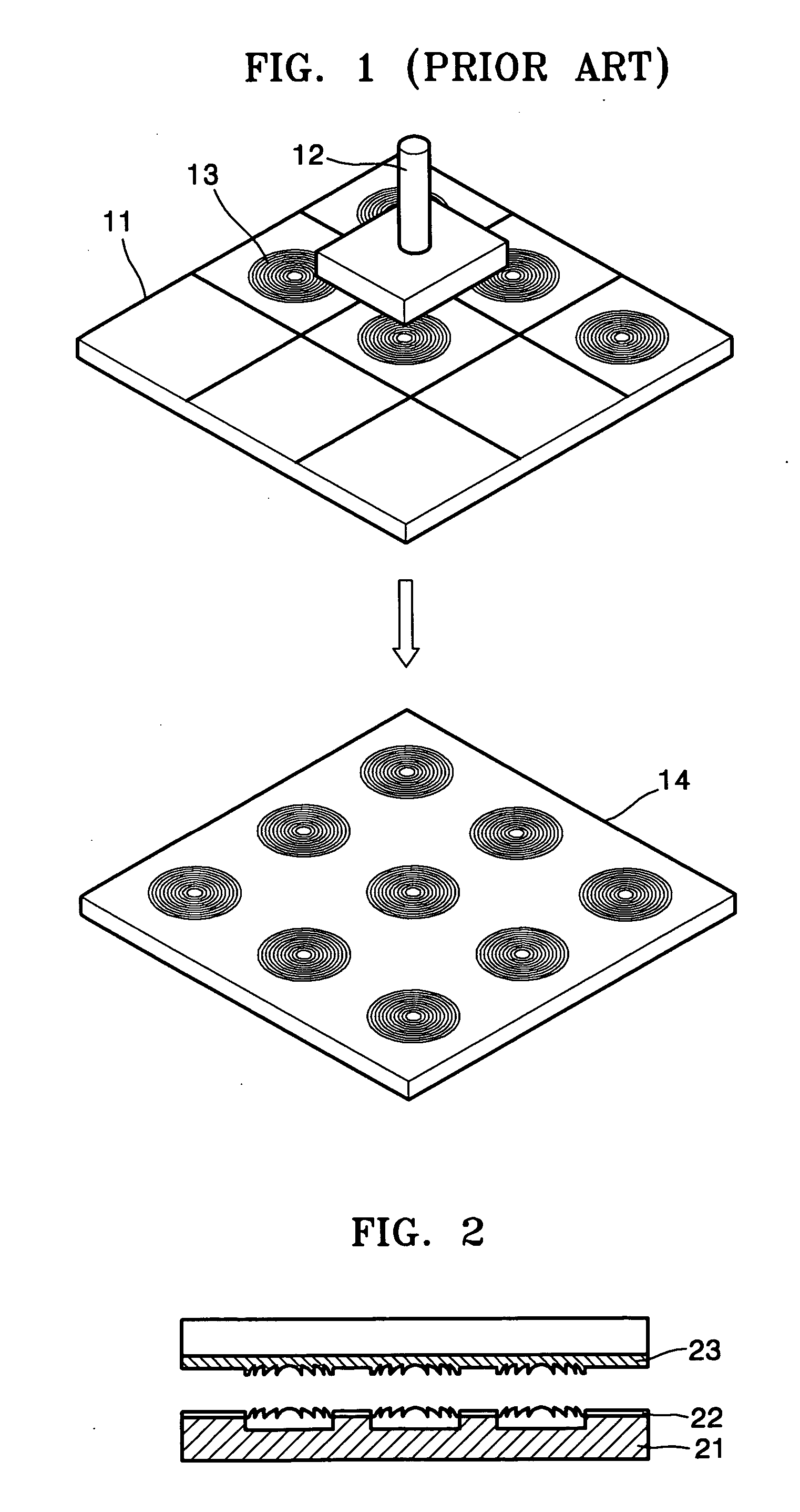
[0026] Referring to FIG. 2, a diffractive lens array 22 is fabricated by an ultraviolet (UV) embossing process. More specifically, a diffractive lens array mold 23 is pressed onto a glass substrate 21 on which a polymer has been coated. Then, the polymer is cured by UV radiation. The polymer is fully cured when heated to a predetermined temperature, thereby fabricating the diffractive lens array 22. A solution containing (Si, Ti)O2 precursors may be used instead of the polymer and has characteristics similar to a glass material when cured by UV radiation. Since refractive index varies depending on the precursor, the use of the solution can improve optical performance. Forming a desired diffractive lens array and an inverted mold structure is essential to fabrication of the diffractive lens array 22.

[0027] A pr...


PUM


Abstract

A method of fabricating a diffractive lens array mold and an ultraviolet (UV) dispenser for use in the same. The method includes the steps of (a) fabricating a single or array diffractive lens mold using a nickel (Ni) shim; (b) fabricating a first diffractive lens array mold using an ultraviolet (UV) dispenser including the single diffractive lens mold; and (c) fabricating a second diffractive lens array mold having an inverted profile of the first diffractive lens array mold.

Description

[0001] This application claims the priority of Korean Patent Application No. 2003-88414, filed on Dec. 6, 2003, in the Korean Intellectual Property Office, the disclosure of which is incorporated herein in its entirety by reference. BACKGROUND OF THE INVENTION [0002] 1. Field of the Invention [0003] The present invention relates to a process for fabricating a diffractive lens array mold and an ultraviolet (UV) dispenser, and more particularly, to a method of fabricating a diffractive lens array mold using a UV embossing process that significantly reduces alignment error and a UV dispenser used during fabrication of the diffractive lens array mold. [0004] 2. Description of the Related Art [0005] Replication techniques such as hot embossing, molding or casting and transfer of a microstructure are used for mass production of diffractive optical elements (DOEs) or micro-optical elements with patterns of micron- and nanometer-scale dimensions. Hot embossing or injection molding is employ...

Claims


Application Information

Patent Timeline
IPC IPC(8): B29D11/00G02B5/18G02B3/00G02B3/08
CPCG02B3/0031G02B5/1885G02B5/1876G02B3/08G02B5/18
Inventor CHO, EUN-HYOUNGLEE, MYUNG-BOKSOHN, JIN-SEUNGJUNG, MEE-SUKKIM, HAE-SUNG
Owner SAMSUNG ELECTRONICS CO LTD
Why Eureka
Try Eureka