Weight balancer and pipe joining method

a weight balancer and pipe technology, applied in the direction of manufacturing tools, soldering devices, auxillary welding devices, etc., can solve the problems of long welding operation time, difficult manual pipe alignment operation, and inability to quickly perform welding operation of the pipe, so as to reduce the alignment error, improve welding quality, and maximize the effect of pipe alignment quality

Active Publication Date: 2014-05-06
SAMSUNG HEAVY IND CO LTD
View PDF12 Cites 0 Cited by
  • Summary
  • Abstract
  • Description
  • Claims
  • Application Information

AI Technical Summary

Benefits of technology

[0045]The pipe joining method of the present invention proposes a specific method of precisely aligning the over-weighted fitting portion to the pipe, thereby enabling to remove the alignment error.
[0046]Further, the pipe joining method of the present invention does not generate the malfunction caused by the cross-interference between the pipe and the fitting portion, thus the pipe alignment quality can be maximized and the weld quality can be improved.
[0047]Further, the pipe joining method of the present invention adopts the integral controller and links the weight balancer with the automatic pipe aligning device, thus the fitting portion and the pipe can be arranged rapidly in a state that the static or dynamic load, the inclination, the vibration, and the weight or weight imbalance are reduced.

Problems solved by technology

That is, pipes through which various fluids, gases, electrical connections or the like might pass are installed as complicatedly as cobwebs.
However, the manual pipe aligning operation like this is very difficult when the second pipe is long in length and heavy in load, and includes a disadvantage in that an operation time for aligning and welding the pipes takes long depending on the height, angle, location, vibration and the like of the pipe even if the operator is a skilled one, especially when there is an imbalance state such that the center of gravity is eccentric from the center of volume according to the shape of the second pipe.
Further, the welding operation of the pipe cannot be performed quickly because of the difficulty to perform the manual pipe aligning operation in a precise manner.
However, the pipe joining operation according to the prior art includes a problem in that the operation time does not only consume a lot of time as it is progressed manually, but the deviation of the weld quality is also very inconsistent depending on the proficiency of the operator.
Thus, there is a disadvantage in that, when the pipe joining operation is not performed in a smooth manner, it affects the subsequent welding operation for the pipe at later.
Further, the pipe joining operation according to the prior art is more difficult when the pipe is large.
However, the pipe joining operation according to the prior art includes an inconvenience in that the large pipe should be moved in use of the transport device like a separate crane for correcting the roundness because the large pipe includes an excessive weight, e.g., about 600 kg, and a length, e.g., about 6 m, and includes a disadvantage in that the operation time of aligning and welding the pipes takes long due to the height, angle, location, vibration and the like of the pipe even though the operator is highly skilled because there is an imbalance state such that the center of gravity is eccentric from the center of volume in accordance with the shape of the pipe, e.g., bent pipe, elbow, T-pipe and the like.
Further, in order to prevent oxidization and nitrification in the welding process, expensive argon (Ar) gas is injected into all the space within the pipe, and the injected argon gas is discharged to the air through an opening portion of both side ends of the pipe, thus there is a problem in that a gas pursing cost is increased.
However, there has been found a difficulty with regards to the automatic pipe aligning device of the Patent Reference 1 in aligning pipes while overcoming the weight of a fitting portion of one pipe to be aligned to another pipe.
For example, in case that the weight and length of the pipe corresponding to the fitting portion is about 600 kg and 6 m, there occurs a case that the six degrees of freedom motion is not realized because a six axis parallel robot like stewart-gough platform installed within the automatic pipe aligning device cannot support the weight of the fitting portion, thereby failing to align or fit the pipes.
Thus, an excessive load might be given to the fitting portion and the automatic pipe aligning device, there might occur damages such as scratch and the like in the fitting portion, and the clamping location of the automatic pipe aligning device and the fitting portion might be changed.
Further, the automatic pipe aligning device of the prior art does not consider a co-operative operation with a separate weight balancer, but only proposes the automatic pipe aligning method by the automatic pipe aligning device, thus in fact there occurs much difficulty in automatically aligning pipes because there was no mention for the method of joining them together with the weight balancer.
For example, the automatic pipe aligning method of the prior art includes a disadvantage in that the clamping location is unstable and the precision of correcting the true circle or of aligning the pipe and the fitting portion is relatively low because no action is disclosed for balancing the device right before clamping.
However, in case that the weight balancer is used in the automatic pipe aligning device of the prior art, a load for the fitting portion which is a payload cannot be reduced actively, and cannot support the fitting portion while translationally moving or rotating to correspond to the 6 degrees of freedom.
Further, the upper portion of the weight balancer supporting the fitting portion is fixed, thereby resulting in a problem that the friction is generated, as mentioned above, between the fitting portion and the upper portion of the weight balancer.

Method used


Image

  • Weight balancer and pipe joining method
  • Weight balancer and pipe joining method
  • Weight balancer and pipe joining method

Examples


Embodiment Construction

[0057](Weight Balancer)

[0058]Preferred embodiments of the present invention will be described in detail with reference to the accompanying drawings.

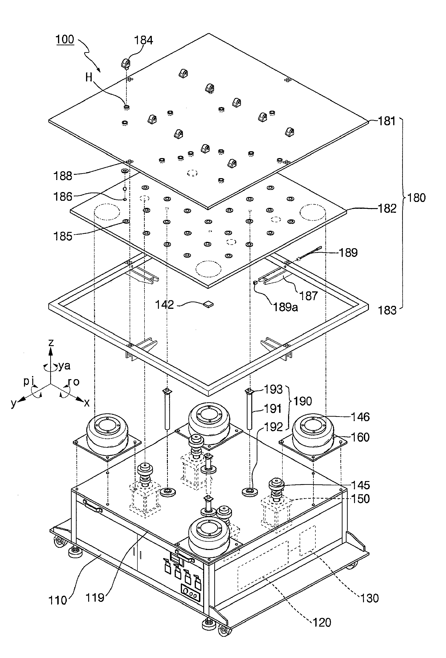
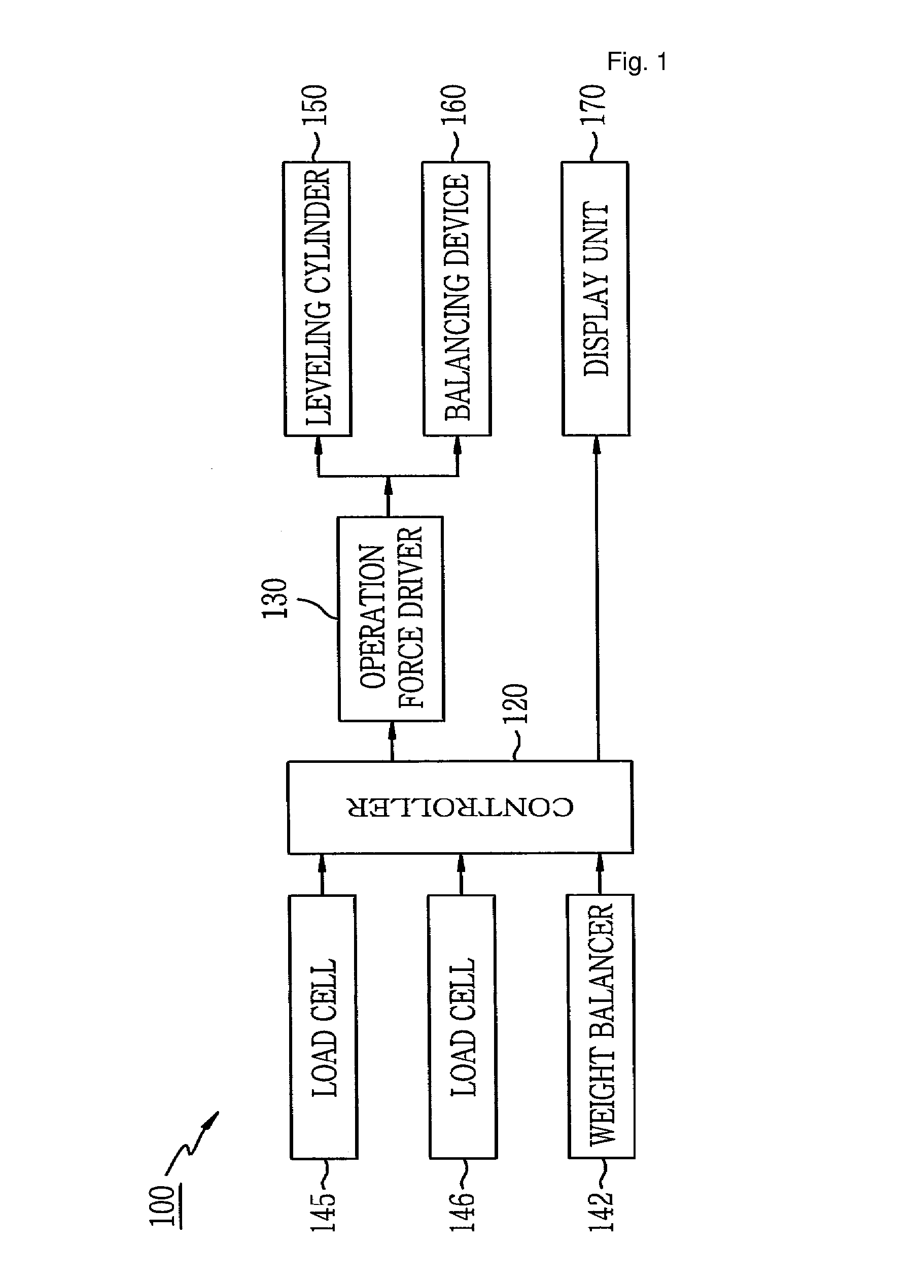
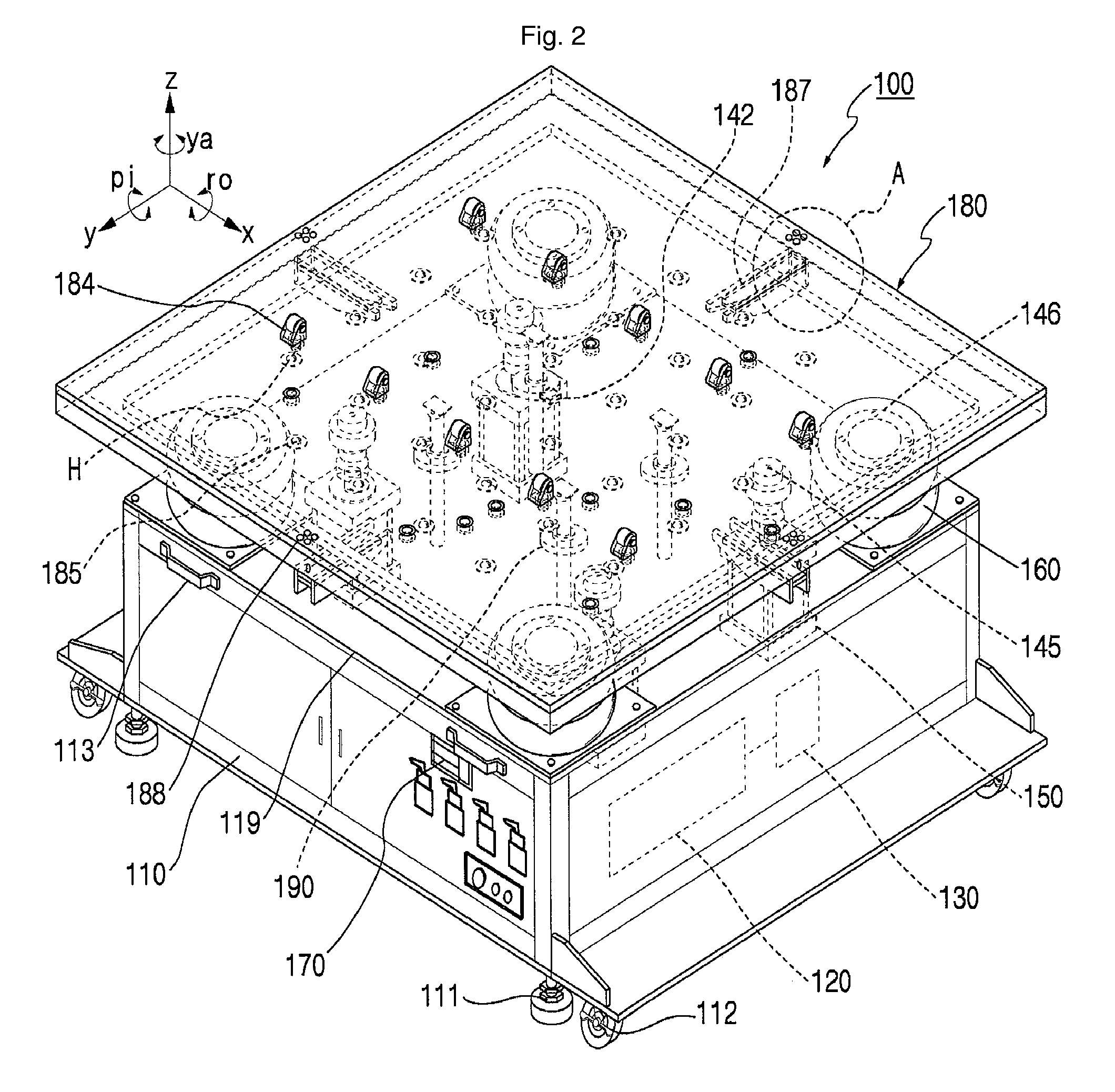
[0059]As shown in FIGS. 1 and 2, a weight balancer according to an embodiment of the present invention includes a controller 120 and an operation force driver 130 within a body frame 110 of a box shape.

[0060]The controller 120 includes a power supply circuit which is connected to an external power source or a self power source, e.g., storage battery, and which can generate operational power that can be used in various sensors, the operation force driver 130, a leveling and balancing operation process module, an input / output circuit composition and the like.

[0061]The leveling and balancing operation process module of the controller 120 analyzes a static load, e.g., a single load transmitted in up and down directions, or a dynamic load, e.g., a plural load transmitted complexly, by a translational motion (surge, sway, heave) and a rotation...


PUM

PropertyMeasurementUnit
lengthaaaaaaaaaa
weightaaaaaaaaaa
diameteraaaaaaaaaa

Abstract

The present invention relates to a weight balancer (100) and a pipe joining method that is capable of reducing a load of pipes when arranging and welding the pipes in ships, plants, piping work sites and the like. A weight balancer (100) according to the present invention includes an operation plate (180) for putting an alignment object; a plurality of load cells (145,146) installed in the lower portion of the operation plate (180); a controller (120) which receives a detection signal generated from the load cell (145,146) and analyzes the information of the alignment object to generate a control signal; an operation force driver (130) which receives the control signal from the controller (120) to control an operational pressure of each of a plurality of pressure supply lines; and a plurality of leveling cylinders (150) and balancing devices (160) which are connected to the pressure supply lines to control a location or pose of the operation plate (180) so as to correspond to the size of the operational pressure controlled by the operation force driver (130).

Description

TECHNICAL FIELD[0001]The present invention relates to a weight balancer and a pipe joining method; and, more particularly, to a weight balancer and a pipe joining method that is capable of reducing a load of pipes when arranging and welding the pipes in ships, plants, piping work sites and the like.BACKGROUND ART[0002]There are many light or heavy pipes in ships, plants, piping work sites and the like. That is, pipes through which various fluids, gases, electrical connections or the like might pass are installed as complicatedly as cobwebs.[0003]In reality, since such pipes are limited in length, a welding operator welds a plurality of pipes to one another to make the pipe in a desired length.[0004]Particularly, even a single pipe used in main pipe lines and the heavy weight pipes are interconnected to be made into relatively long pipes while being suitable for a pipe line or plumbing design.[0005]Herein, a reference pipe (hereinafter, referred to as ‘first pipe’) and a pipe (herein...

Claims


Application Information

Patent Timeline
Patent Type & Authority Patents(United States)
IPC IPC(8): B23K20/00
CPCB23K2201/06B23K37/0531B23K37/047B23K2101/06Y10T29/49778
Inventor CHO, KI-SOOPARK, YOUNG-JUNPARK, SUN-KYUCHUNG, SEONG-YOUBCHANG, HONG-RAEHA, YOUNG-YOULKIM, SUNG-JOONPARK, JONG-IL
Owner SAMSUNG HEAVY IND CO LTD
Why Eureka
Try Eureka