Method for monitoring the course of a process using a reactive gas containing one or several hydrocarbons

a technology of reactive gas and process, which is applied in the direction of weighing by absorbing component, extraction purification/separation, and process separation, etc., can solve the problems of microstructure modification, infiltration conditions change, and risk of a modification of the deposited matrix material microstructure, so as to avoid clogging up the pipework, eliminate tars, and eliminate tars

Inactive Publication Date: 2005-07-28
MESSIER BUGATTI INC
View PDF8 Cites 13 Cited by
  • Summary
  • Abstract
  • Description
  • Claims
  • Application Information

AI Technical Summary

Benefits of technology

[0016] The Applicant has found that merely monitoring the quantity of tar absorbed by an oil used for washing the effluent gas provides a reliable indication concerning the progress of the process, without requiring recourse to complex apparatus and while being entirely suitable for integration in an installation for processing effluent gas. In order to avoid clogging up pipework and in order to satisfy environmental requirements, it is highly desirable to treat the effluent gas so as to eliminate the tars. Eliminating tars by washing in oil is a treatment method that is effective. The present invention can take advantage of the use of such a treatment method for the purpose of continuously monitoring the process in a manner that is simple and inexpensive.

Problems solved by technology

Unfortunately, infiltration conditions change as the process advances because the initial pores within the substrate become progressively filled in.
The selected parameters thus result from seeking the best compromise between the optimum that is suitable for the beginning of densification and the optimum that is suitable at the end of densification, but with a risk of a modification to the microstructure of the deposited matrix material because of the changing pore size of the substrates, i.e. the changing geometrical characteristics of the pores.
Nevertheless, that variation is undertaken in application of a pre-established model, and does not take account of the real progress of the process.

Method used


Image

  • Method for monitoring the course of a process using a reactive gas containing one or several hydrocarbons
  • Method for monitoring the course of a process using a reactive gas containing one or several hydrocarbons

Examples


Embodiment Construction

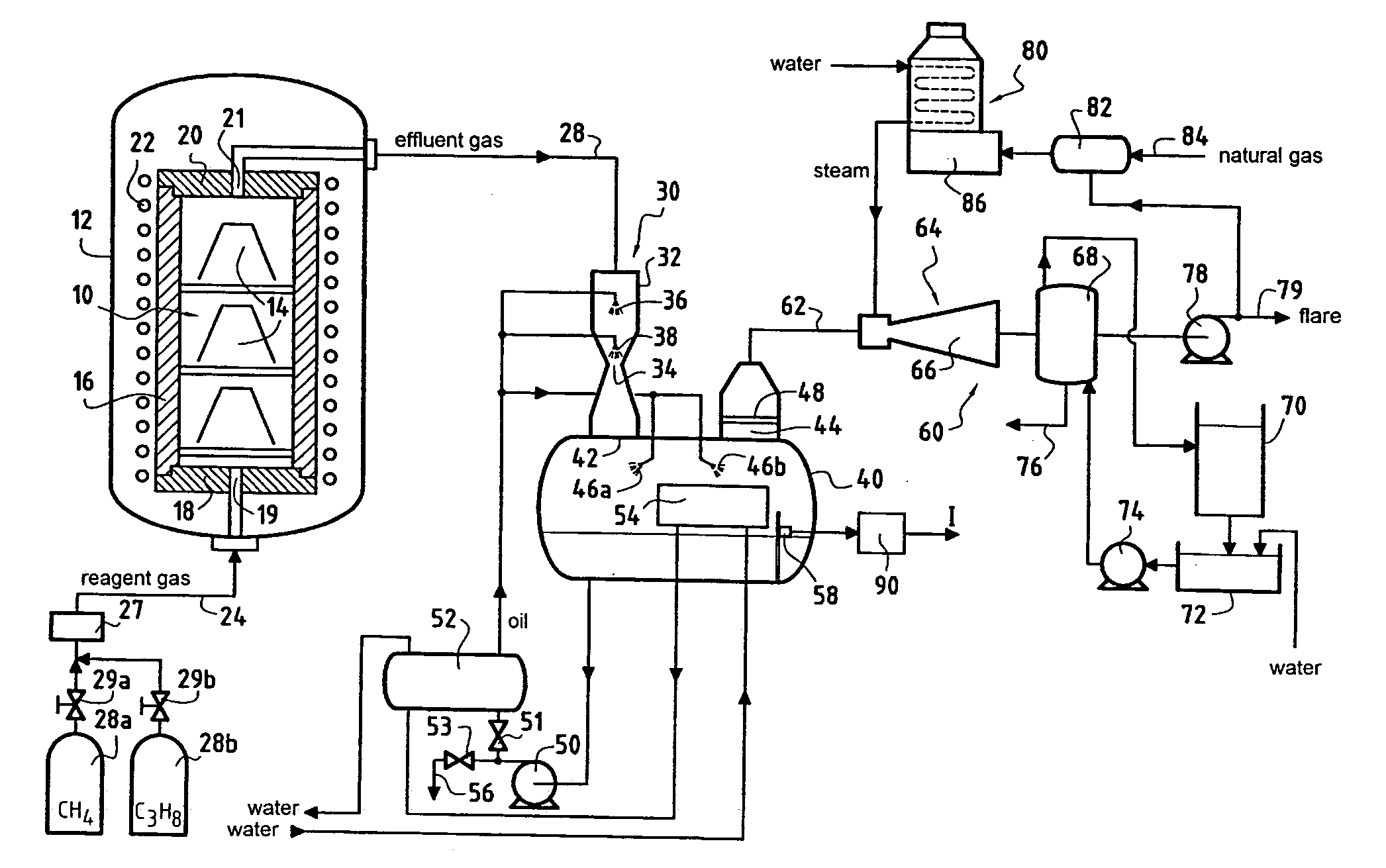
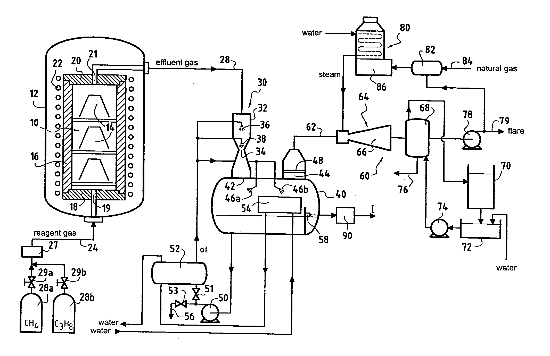
[0018]FIG. 1 shows in highly diagrammatic manner a chemical vapor infiltration installation for densifying porous substrates with a pyrolytic carbon matrix. The chemical vapor infiltration process may be of the isothermal-isobaric type, i.e. without using a temperature gradient or a pressure gradient across the substrate, or it may be of the temperature gradient type, i.e. with the substrate being heated non-uniformly, or it may be of the pressure gradient type, i.e. having different pressures on opposite faces of the substrates.

[0019] An oven 10 housed in a casing 12 receives porous substrates 14 for densification, for example fiber preforms for parts that are to be made out of carbon-matrix composite material. Examples of fiber preforms are preforms for divergent portions or divergent portion elements of rocket engine nozzles, or preforms for C / C composite brake disks. The oven 10 is defined by a susceptor-forming side wall 16, e.g. made of graphite, together with a bottom 18 and...


PUM

PropertyMeasurementUnit
pressureaaaaaaaaaa
vapor pressureaaaaaaaaaa

Abstract

The method applies to a process such as cementation or chemical vapor infiltration or deposition, the process being carried out in an oven and the method comprising setting operating parameters of the oven, introducing a reagent gas into the oven, the reagent gas containing at least one gaseous hydrocarbon, and extracting from the oven an effluent gas containing reaction by-products of the reagent gas. The effluent gas is subjected to washing in oil that absorbs tars contained in the effluent gas, and information about the progress of the process is obtained by measuring the quantity of tar absorbed by the oil.

Description

BACKGROUND OF THE INVENTION [0001] The invention relates to processes making use of a reagent gas containing one or more gaseous hydrocarbons, in particular processes for cementation of parts, for forming coatings of pyrolytic carbon on substrates by chemical vapor deposition (CVD), or for densifying porous substrates with a pyrolytic carbon matrix formed by chemical vapor infiltration (CVI). [0002] One particular, but non-exclusive, field of application of the invention lies in making composite material parts comprising a fiber reinforcing substrate or “preform” densified by a matrix of pyrolytic carbon, and in particular carbon / carbon (C / C) composite material parts. [0003] Substrates for densification are placed in an oven into which a reagent gas containing one or more precursors is introduced at low pressure. The precursor is constituted by one or more gaseous hydrocarbons, typically methane, propane, or a mixture thereof. The operating parameters of the oven are adjusted so as ...

Claims


Application Information

Patent Timeline
Patent Type & Authority Applications(United States)
IPC IPC(8): G01N5/02B01D53/14C23C16/00C23C16/04C23C16/26C23C16/44C23C16/52
CPCB01D53/1487C23C16/045C23C16/52C23C16/4412C23C16/26
Inventor DELPERIER, BERNARDTHIBAUDEAU, ERIC
Owner MESSIER BUGATTI INC
Why Eureka
Try Eureka