Cassette for isolation, amplification and identification of DNA or protein and method of use

a technology of dna and protein, which is applied in the field of cassettes, can solve the problems of time and expense saving, silicon suffers, and the cost of silicon microfluidic devices can be relatively high, and achieves the effect of reducing the cost of silicon microfluidic devices and reducing the cost of silicon fabrication

Inactive Publication Date: 2005-08-11
JONES BRIAN
View PDF9 Cites 53 Cited by
  • Summary
  • Abstract
  • Description
  • Claims
  • Application Information

AI Technical Summary

Benefits of technology

[0009] It is preferred that the cassette of the present invention further includes a waste chamber in fluid communication with the isolation chamber and suitable for receiving undesired cellular components, unused sample or reagents or all of the above. Typically, the waste chamber is in fluid communication with the isolation chamber by a first channel. Preferably, the first channel has a first valve operatively positioned therein. By the term “operatively positioned” is meant that the valve is capable of allowing or preventing the flow of liquid in the channel in which it is positioned.
[0018] In one embodiment, the strip of elastomer is positioned between the top plate and the opposing bottom plate. In another embodiment, a valve cluster, comprising a strip of elastomer is adhered via injection molding to the outside face of the top plate or bottom plate of the cassette. A hole (valve port) extending between the top and bottom surfaces of one of the plates connects one face of the adhered elastomeric rubber to the channel below and allows a pin to compress the elastomeric rubber down the hole (valve port) and across the channel to completely occlude the channel.
[0019] It is also within the scope of the present invention that one or both plates of the cassette of the present invention further comprises a thin elastomeric layer or coating positioned along the edge of the chambers and channels to provide a watertight seal when the surfaces of the top plate and the bottom plate are mated and there is liquid therein. In this embodiment, the layer is typically about 0.010 to 0.090 inches thick; more typically about 0.030 to 0.70 inches; most typically about 0.050 inches thick. In this embodiment, the elastomeric layer provides a compression seal when the surfaces are mated together and allows for minor defects in the molding of the plates.

Problems solved by technology

Next, the DNA is typically separated from the rest of the cell contents, as the presence of other cell contents may be undesirable in subsequent steps.
The ability to perform all of these steps in a single miniaturized device has the potential for saving time and expense.
Silicon, however, suffers from a number of disadvantages as a substrate material.
The cost of fabricating microfluidic devices in silicon can be relatively high.
Silicon's high thermal conductivity can make the thermal cycling needed to perform PCR difficult, and silicon's property of being electrically semiconducting can hamper the operation of components that require the maintenance of a high potential difference.
Most importantly, the difficulty of bonding multiple layers of silicon together makes it difficult to integrate complex components into the device.
The raw materials for the green-sheet layers are expensive as is the sintering process.

Method used


Image

  • Cassette for isolation, amplification and identification of DNA or protein and method of use
  • Cassette for isolation, amplification and identification of DNA or protein and method of use
  • Cassette for isolation, amplification and identification of DNA or protein and method of use

Examples


example 1

Making a Cassette of the Present Invention

[0075] The bottom plate of the cassette comprised of a UV transparent acrylic was placed face up on solid surface. A silk screen assembly manufactured by AsahiTec America, Richmond, Ind. and modified to align with the bottom plate was positioned over the bottom plate and suspended ˜1-2 mm above the bottom plate. The silk screen was 330-mesh polyester; 35μ thread diameter; 42μ mesh opening and had a 56±3μ overall thickness. A bead of U.V.-curable adhesive was manually applied directly to the silk screen (i.e., above the silk screen pattern). A squeegee (#CPS-5070 with wood handle, 70-75 durometer (Shore ‘A’ scale), A.W.T. World Trade, Inc., Chicago, Ill.) with square-edge tip was dipped into the adhesive bead on the silk screen (see above). Starting at the top of silk screen pattern, adhesive was applied to the silk screen pattern with the squeegee tip at 45-degree angle (to the perpendicular) while maintaining constant squeegee pressure an...

example 2

DNA Assay Using the Four Mixing Chamber Embodiment (FIG. 5) of the Cassette of the Present Invention

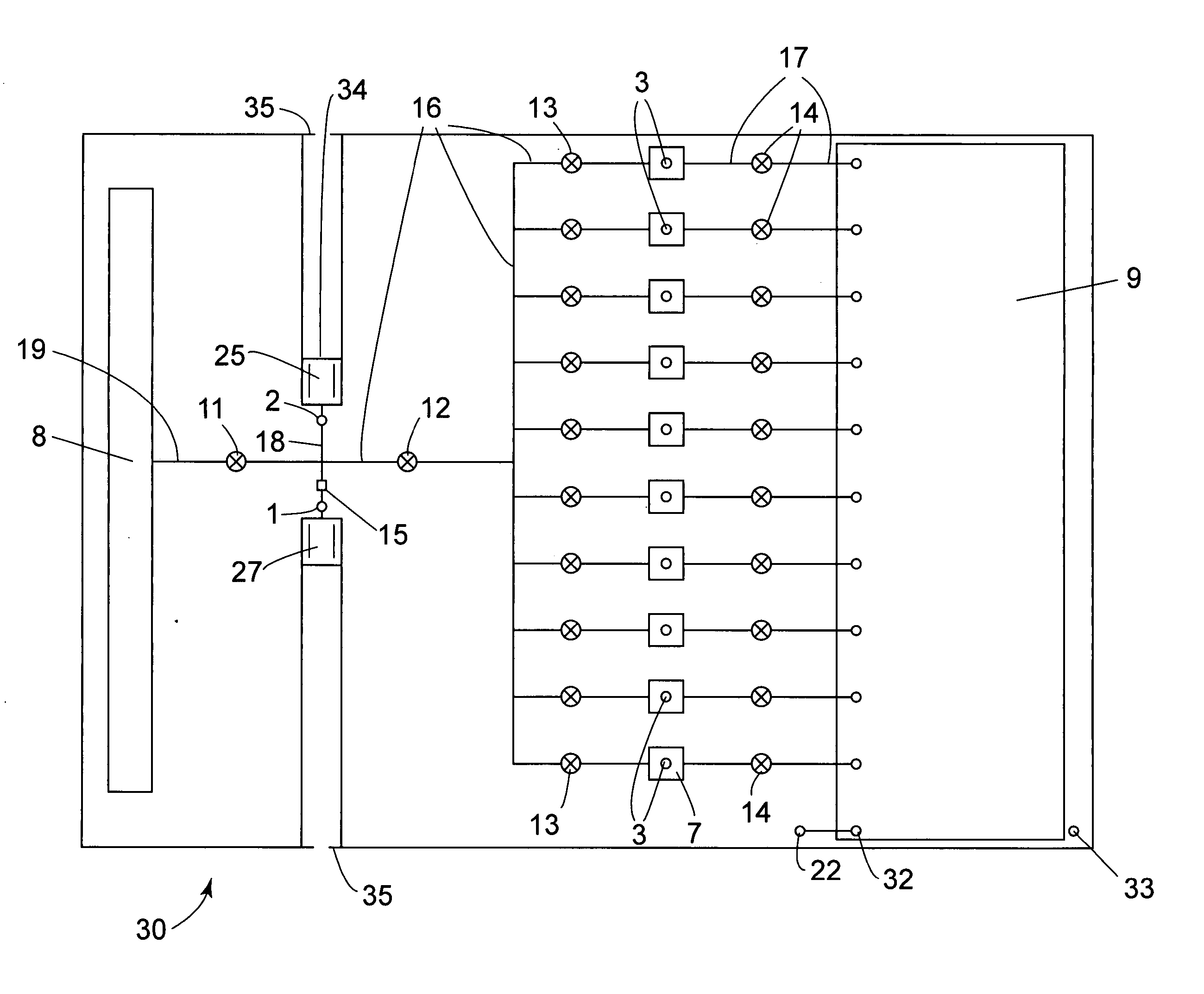
[0077] The cassette of FIG. 5 is removed from its sterile pouch and placed into the nest of an appropriate instrument. Valves 11, 12 and 43 are placed in the closed position. Pistons 25, 27, 45 and 47 are in the closed (home) positions. Four piston shafts engage the proximal ends of the four pistons, respectively, and seat therein. A biological sample (100 μL) containing nucleated cells suspected of containing target DNA is injected from a sample syringe into a first mixing chamber (MC) 5 through sample port (SP) 1. The piston 27 in MC 5 is retracted sufficiently to intake the 100 μL of sample. Lysis solution (50 μL) from reagent syringe #1 was then added to MC 5 via SP 1. The piston 27 in MC 5 is retracted sufficiently to intake the 50 μL of lysis solution. Mixing of both solutions was achieved by repeated transfers (cycling 3×) of the total volume between MC 5 and MC 6 using pisto...

example 3

Protein Assay Using the Two Mixing Chamber Embodiment (FIG. 3) of the Cassette of the Present Invention

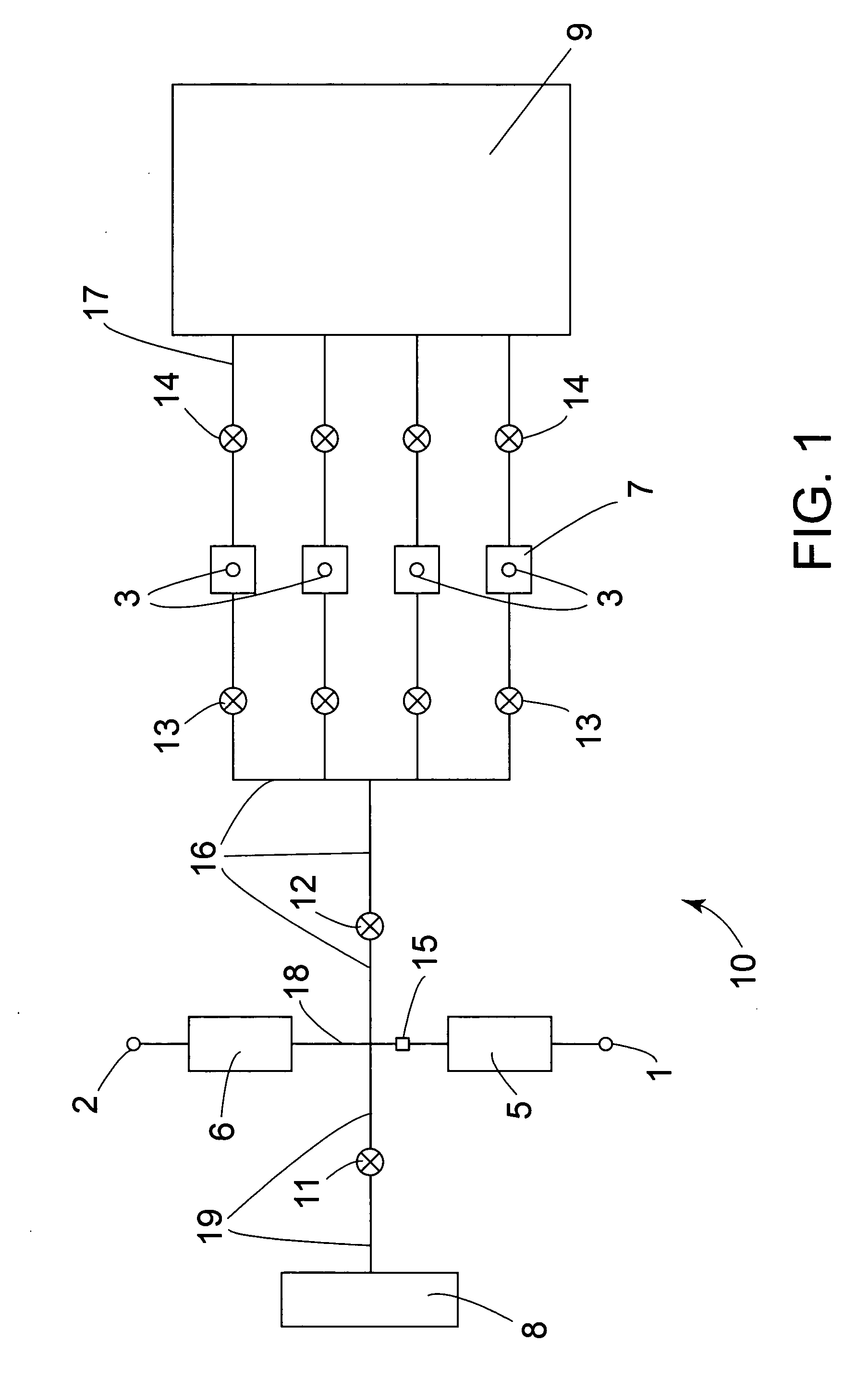
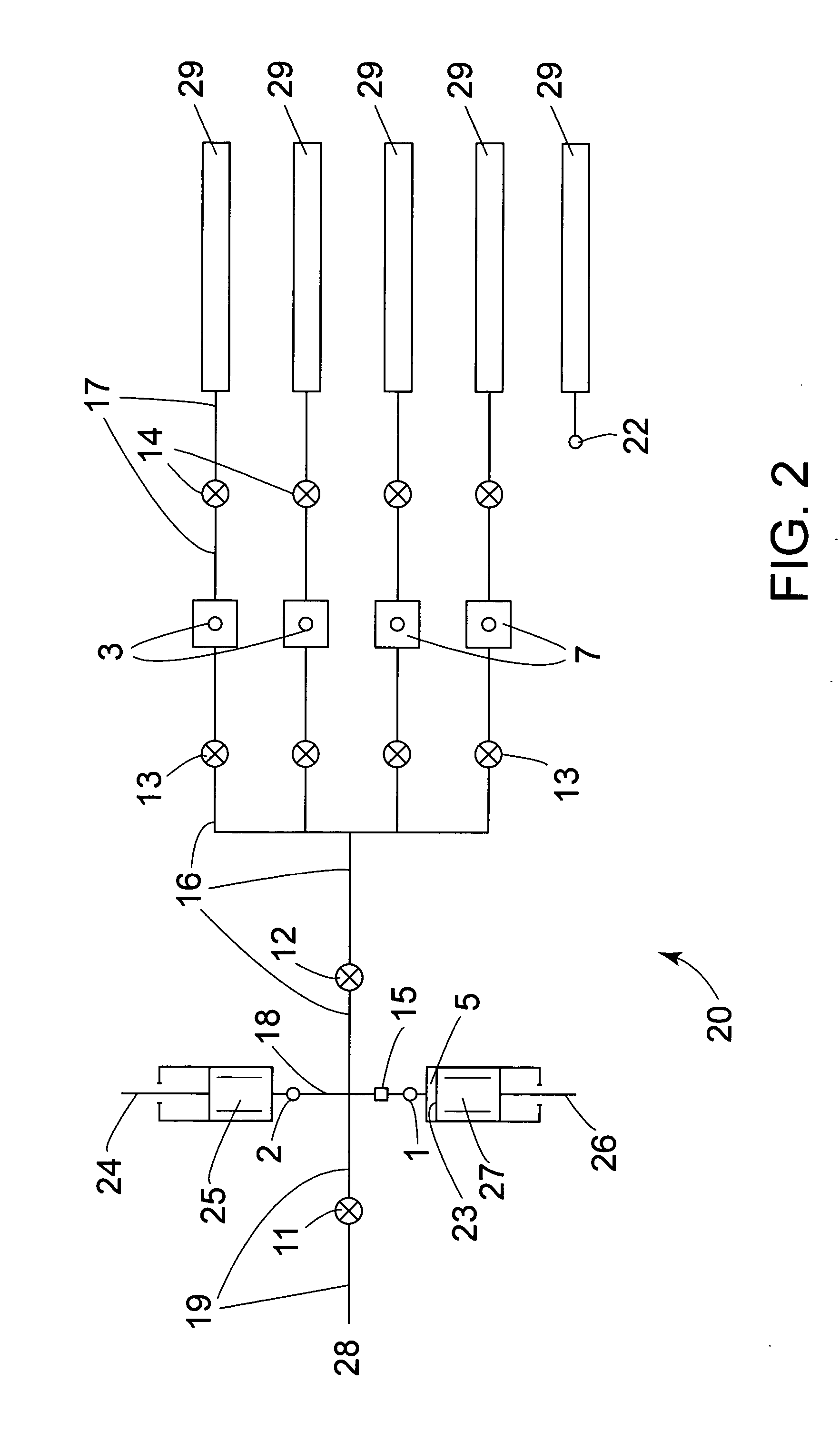
[0078] The cassette of FIG. 3 is removed from its sterile pouch and placed into the nest of an appropriate instrument. Valves 11 and 12 are placed in the closed position. Pistons 25 and 27 are in the closed (home) positions. Two piston shafts engage the proximal ends of the four pistons, respectively, and seat therein. A biological sample (100 μL) is injected from the sample syringe (located on instrument carousel) into a mixing chamber (MC) 5 through sample port (SP) 1 while the instrument simultaneously withdraws piston 27 of MC 5 a corresponding amount to intake the volume of sample. Preferably, the biological sample is prepared to be debris and stroma free outside the cassette. A reagent dispenser outside the cassette dispenses into SP 1 75 μL of a suspension of latex beads (diameter of 2 microns or greater) having a target specific antibody thereon. Simultaneously, piston 27...


PUM

PropertyMeasurementUnit
wavelengthsaaaaaaaaaa
thickaaaaaaaaaa
thickaaaaaaaaaa

Abstract

The present invention is directed to a device for DNA analysis. More particularly, the present invention is directed to a cassette which comprises a first chamber suitable for isolating DNA from a biological sample that is suspected of containing a target DNA, one or more second chambers suitable for amplifying any target DNA found in the sample, a chamber suitable for digesting the target DNA with restriction endonucleases, a medium for separation of the digestion fragments, and a channel connecting the digestion chamber to the separation medium and being of suitable size for transferring at least a portion of the contents of the digestion chamber to the separation medium. Typically, the medium for separation of the digestion fragments is an electrophoretic medium. The cassette of the present invention can also be used for the separation and identification of a protein of interest in a biological sample. It is within the scope of the present invention that the cassette also contains one or more internal waste chambers into which used reagents and biological sample can be directed and stored for disposal with the cassette. It is also within the scope of the present invention that the cassette contains a chamber for storage or receipt of a biological control sample.

Description

BACKGROUND OF THE INVENTION [0001] The present invention relates to devices for DNA and / or protein analysis. More particularly, the present invention relates to cassettes which are useful for isolating DNA and / or protein from a biological sample suspected of containing a target DNA or a target protein and ultimately identifying whether the DNA or protein in the sample contains the target DNA or target protein. In the case of DNA, the cassette also provides one or more reaction chambers for the amplification of the target DNA to provide it in a detectable amount. The cassettes of the present invention are useful for screening for a plurality of target DNA molecules in a single sample and have a plurality of uses, including diagnostic medicine, and in the identifying the presence of pathogenic organisms or toxic proteins on foods or surfaces. [0002] The conventional way of analyzing the DNA present in a sample of cells involves performing multiple steps using several different bench t...

Claims


Application Information

Patent Timeline
Patent Type & Authority Applications(United States)
IPC IPC(8): C12M1/34
CPCB01L3/502707B01L2400/0655B01L3/502738B01L3/502753B01L7/52B01L2200/0689B01L2200/10B01L2200/12B01L2300/0681B01L2300/0816B01L2300/0864B01L2300/0867B01L2300/0887B01L2300/1822B01L2400/0421B01L2400/0478B01L2400/0487B01L3/50273
Inventor JONES, BRIAN
Owner JONES BRIAN
Why Eureka
Try Eureka