Engine speed stabilization using fuel rate control

a fuel rate control and engine technology, applied in the direction of electric control, speed sensing governors, instruments, etc., can solve the problems of idle speed stability, speed instability manifesting itself, and none has been able to achieve complete success in overcoming, so as to avoid idle speed instability

Active Publication Date: 2005-08-11
INT ENGINE INTPROP CO LLC
View PDF12 Cites 10 Cited by
  • Summary
  • Abstract
  • Description
  • Claims
  • Application Information

AI Technical Summary

Benefits of technology

[0013] The present invention relates to an improvement in diesel engine control system strategy for avoiding instability in idle speed.

Problems solved by technology

Poor idle speed stability arising from changes in engine load, even small ones, has been recognized as a seemingly inherent operating characteristic of a basic diesel engine.
Speed instability manifests itself by engine speed oscillating and / or wandering in consequence of a load change, rather than quickly stabilizing at a constant speed.
While some improvements have been made over the many years that diesel engines have been in existence, the inventors believe it is fair to state that none has been able to achieve complete success in overcoming this seemingly inherent and undesirable characteristic of such engines.
By their observation that a diesel engine is capable of operating at any of multiple different speeds using approximately the same fuel quantity per stroke, the inventors believe that a governing strategy that controls idle speed using strictly fuel quantity-per-stroke cannot provide an effective solution for idle speed control.
That a known idle speed governor embodying a known governing algorithm acting to control engine fueling via known devices and hardware is prone to instability when operating on a fuel quantity-per-stroke basis, is illustrated by the following situations.
If the idle speed governor is locked to a particular quantity of fuel per stroke in order to run the engine at a desired idle speed, any change that decreases engine speed, such as a change in engine load due to an engine-driven accessory being activated, will necessarily decrease the fueling rate to the engine.
That is exactly the opposite of what the engine actually needs in order to maintain desired idle speed, and consequently idle speed becomes unstable, at least temporarily.
The evolution of electronic diesel engine control systems has resulted in the use of separate electronic modules for engine control and for fuel control, and their presence has created further complications for idle speed governing.
The use of separate ECM and ICM modules has placed added demand on the idle speed governor, tending to make stabilization of idle speed more difficult.
This is essentially due to communications and scheduling delays between the different modules creating phase shift between the instant of time at which engine speed is measured and the instant of time at which a resulting fueling change can occur in consequence of a change in engine speed.
In any feedback control system, an electronic engine governor being one example, phase shift is commonly a limiting factor in tuning the gain of the control loop.
Increasing phase shift tends to make the control less stable and ultimately unstable if the phase shift becomes too large.
The combination of the idle speed instability that is seemingly inherent in a diesel engine and the added phase shift resulting from the use of separate electronic modules is believed counterproductive to the objective of optimizing idle speed control in an engine governor.
If the control loop gain is de-tuned to achieve stability, the engine responds poorly when engine load changes.
If the gain is increased for better response, the system tends toward instability.

Method used


Image

  • Engine speed stabilization using fuel rate control
  • Engine speed stabilization using fuel rate control
  • Engine speed stabilization using fuel rate control

Examples


Embodiment Construction

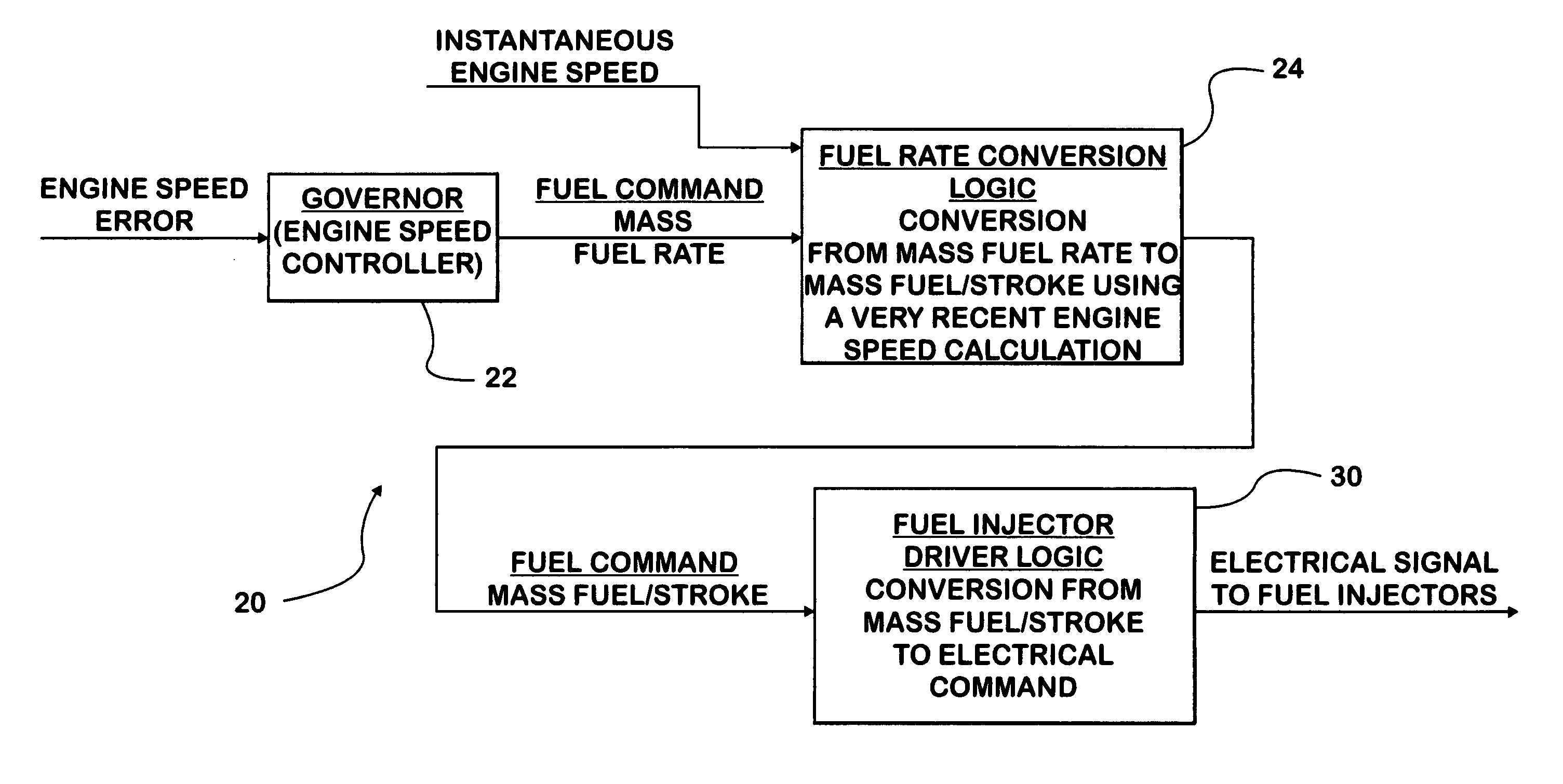
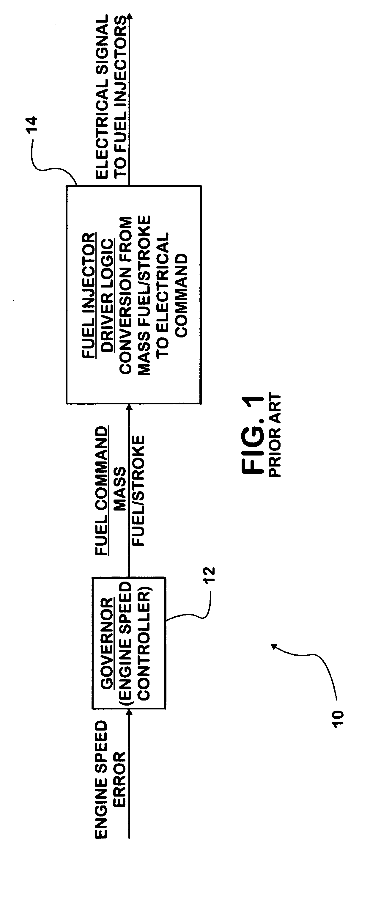
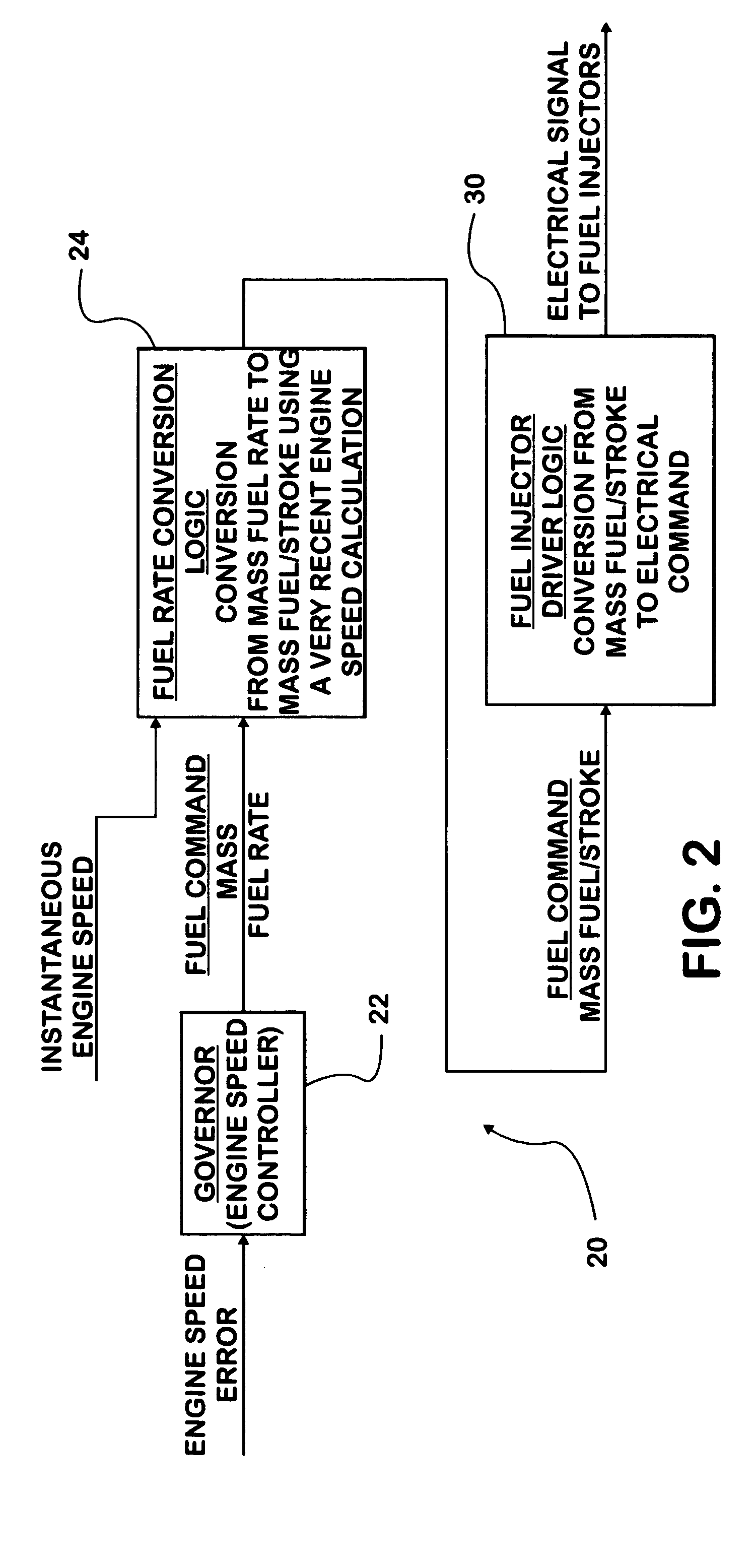
[0029]FIG. 1 shows a known governing strategy 10 for a diesel engine. The strategy can be implemented in a processor-based engine control system using an appropriate algorithm to govern engine idle speed.

[0030] Strategy 10 comprises processing data values for actual engine speed and desired engine idle speed to yield a data value for engine speed error that forms a data input to a governor 12. Governor 12 is implemented, in an ECM for example, as an appropriate governor algorithm programmed into the processing system of the ECM. Governor 12 processes the data value for engine speed error according to the algorithm to yield a data value for engine fueling in terms of quantity-per-stroke, such as fuel mass per stroke in any appropriate unit of measurement, such as milligrams per stroke.

[0031] That data value is communicated to fuel injector driver logic 14 that is present, in an ICM for example, to control fuel injectors of the engine fueling system. Driver logic 14 converts the qua...


PUM


Abstract

Idle speed stability is imparted to a compression ignition engine by processing data values for actual engine speed and desired engine speed to yield a data value for engine speed error; processing (22) the data value for engine speed error according to a governor algorithm for yielding a data value for a mass fuel rate for governed fueling of the engine; c) processing (24) the data value for mass fuel rate for governed fueling of the engine and the data value for actual engine speed to yield a data value for a quantity of fuel to be injected into an engine cylinder during an ensuing stroke of a piston within the cylinder; and d) injecting (30) that quantity of fuel into the cylinder during that stroke.

Description

FIELD OF THE INVENTION [0001] This invention relates generally to internal combustion engines. More specifically it relates to a novel strategy for improving engine idle speed stability, particularly in compression ignition engines. BACKGROUND OF THE INVENTION [0002] Poor idle speed stability arising from changes in engine load, even small ones, has been recognized as a seemingly inherent operating characteristic of a basic diesel engine. Speed instability manifests itself by engine speed oscillating and / or wandering in consequence of a load change, rather than quickly stabilizing at a constant speed. [0003] Various devices, special flyball governors for example, have been added to diesel engines in attempts to secure better speed stability. While some improvements have been made over the many years that diesel engines have been in existence, the inventors believe it is fair to state that none has been able to achieve complete success in overcoming this seemingly inherent and undesi...

Claims


Application Information

Patent Timeline
Patent Type & Authority Applications(United States)
IPC IPC(8): B60T7/12F02D41/08F02D41/16G05D1/00G06F7/00G06F17/00G06F19/00
CPCF02D41/16F02D41/083F02D41/38F02D1/02
Inventor BISHOP, KEVIN P.GORCZOWSKI, WALTER P.SATYAVOLU, SURESH L.
Owner INT ENGINE INTPROP CO LLC
Why Eureka
Try Eureka