System for testing paving materials

a technology for asphalt pavement and characteristics, applied in the direction of material analysis, force measurement, instruments, etc., can solve the problems of thermal shrinkage cracking, cracking of asphalt pavement, moisture damage,

Active Publication Date: 2005-08-18
OHIO UNIV
View PDF19 Cites 19 Cited by
  • Summary
  • Abstract
  • Description
  • Claims
  • Application Information

AI Technical Summary

Problems solved by technology

Low temperature thermal shrinkage cracking is one of four major failure modes in asphalt pavement, together with rutting, fatigue cracking, and moisture damage.
Thermal shrinkage cracking in asphalt pavement occurs when the thermal tensile stress within the asphalt pavement that results from temperature drop exceeds the strength at that temperature.
While effective at generating useful data, these systems are complex, require the performance of numerous calculations, require the testing of many specimens, do not directly measure the temperature at which the specimen fails, and are often very time consuming and expensive to perform.

Method used


Image

  • System for testing paving materials
  • System for testing paving materials
  • System for testing paving materials

Examples


example i

Preparation of Mold and Test Specimen

[0042] A test specimen of asphalt binder may be prepared and analyzed by the following alternative exemplary method.

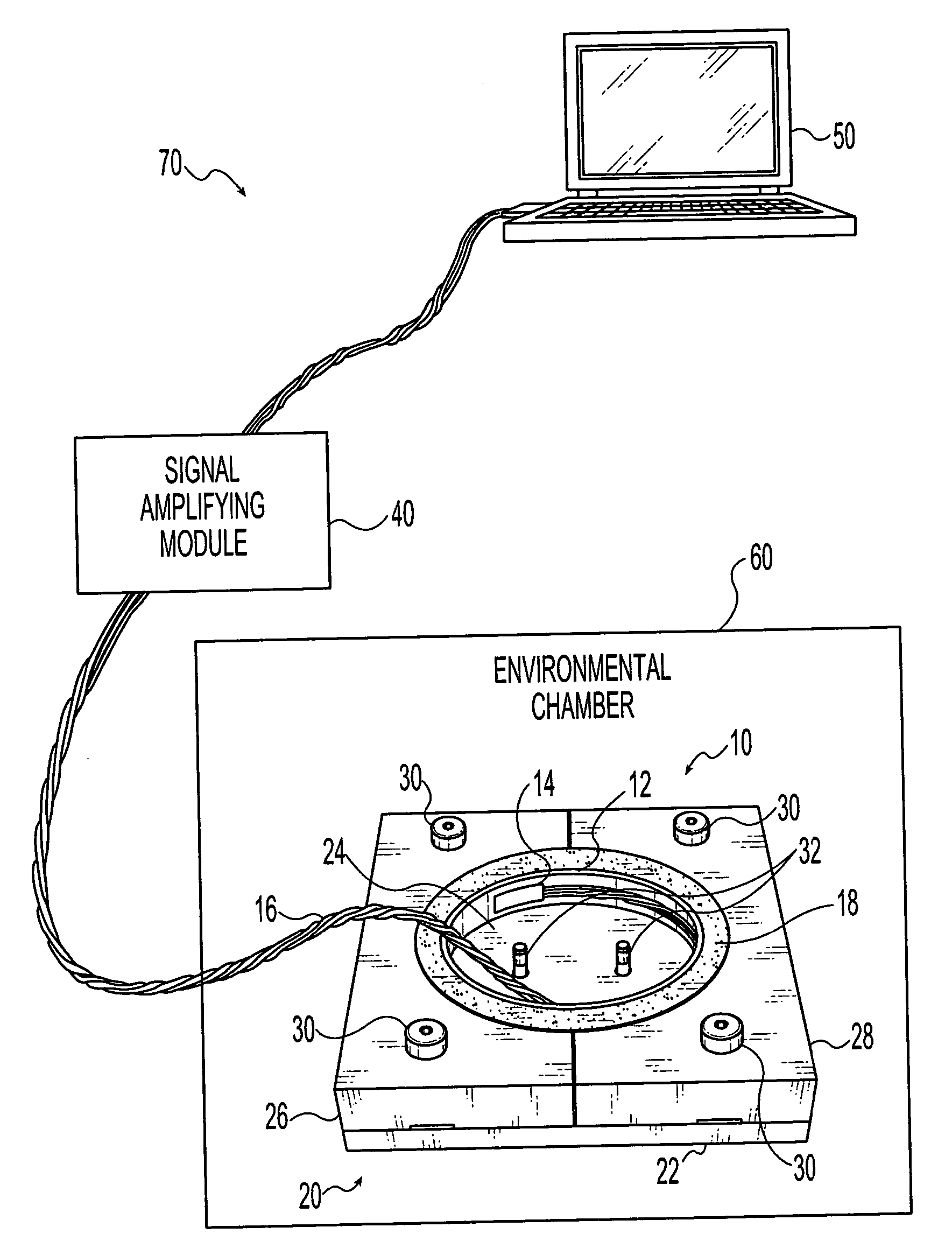
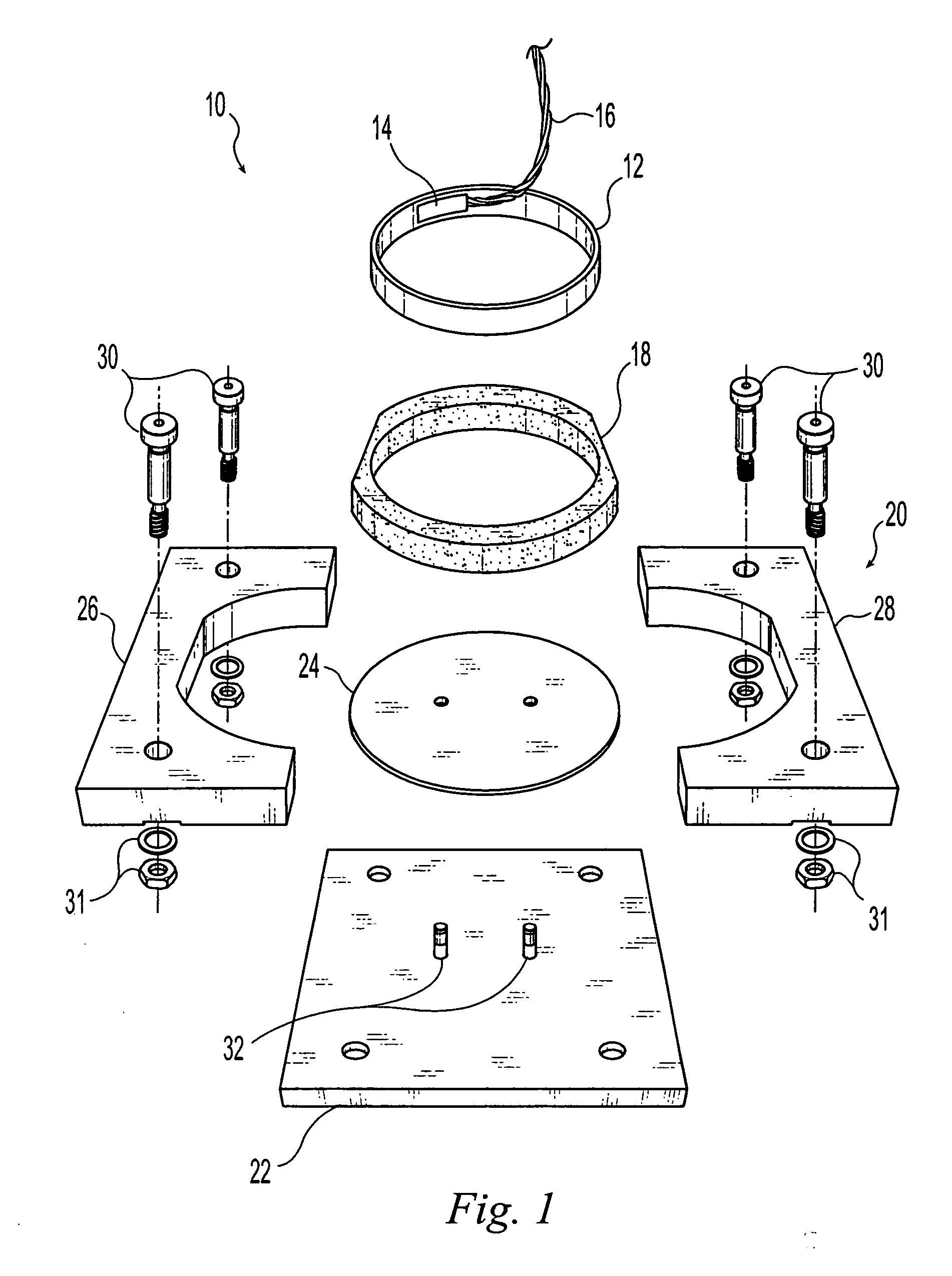
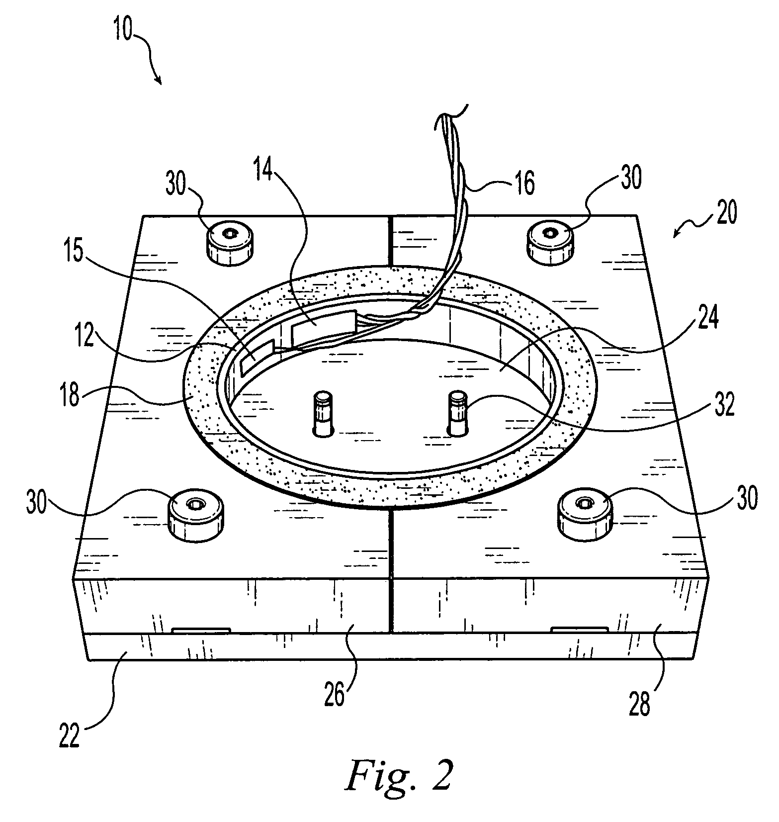
[0043] 1. Assemble one or more aluminum (or steel) molds. Uniform 6.35 mm thick circular asphalt binder specimens are desirable for this exemplary method. Preferably, samples are prepared in triplicate.

[0044] 2. Apply (lightly) high vacuum grease to the exterior surface of ring 12 to prevent bonding between ring 12 and specimen 18 and to reduce any friction between the asphalt binder and the ring surface during the de-molding process (i.e., removal of the specimen from the mold).

[0045] 3. Place thin plastic film (e.g., transparency film for a laser printer) on top of base plate 22 to facilitate removal of specimen 18 following casting; position centering plate 20 and tighten dowel pin(s) 32; and attach specimen supports 26 and 28 with the shoulder bolts 30.

[0046] 4. On the inside, arced surface of specimen supports 26 and 28, p...

example ii

[0079] A test specimen 118 of asphalt binder may be prepared and analyzed by the following alternative exemplary method.

Preparation of Molds and Test Specimens

[0080] 1. An aluminum foil spout is wrapped around the tins in order to provide better control and accuracy when pouring the hot asphalt binder. The tins are then placed in a steel cup to slow heat dissipation when pouring several samples.

[0081] 2. The asphalt binder is heated in the tins for one hour in order to be sufficiently fluid to pour. The AASHTO binder specifications recommend minimum pouring temperature that produces a consistency equivalent to that of SAE 10W30 motor oil (readily pours but not overly fluid) at room temperature. After the initial heating, the asphalt binder samples are degassed in the vacuum oven at 0.09 MPa for 15 minutes to remove entrapped air.

[0082] 3. The silicone molds 120 are prepared by applying a release agent of talc and glycerin (with a 1:1 mass ratio) to the specimen forming surfaces....


PUM

PropertyMeasurementUnit
temperatureaaaaaaaaaa
temperaturesaaaaaaaaaa

Abstract

A system for measuring the critical temperatures for thermal cracking of asphalt binders. The exemplary embodiment comprises a metal ring, at least one strain gauge attached to the inner surface of the ring, an environmental chamber, and a data acquisition system. A thermocouple may also be attached to the inside of the ring to monitor the ring temperature. A mold is provided for creating a circular asphalt binder test specimen. When properly cast, the specimen encircles the metal ring. The specimen and ring are placed within the environmental chamber for analysis as the temperature within the chamber is lowered. Thermal stress induced by temperature reduction within the asphalt binder test specimen is monitored by the strain gauge(s) and the cracking temperature is directly determined from the strain reading.

Description

CROSS-REFERENCE TO RELATED APPLICATIONS [0001] This application is a continuation-in-part of U.S. patent application Ser. No. 10 / 524,907, filed on Feb. 17, 2005 and entitled “Device and Method for Testing Paving Materials,” which claimed priority to PCT application PCT / US03 / 26459, filed on Aug. 22, 2003 and entitled “Device and Method for Testing Paving Materials,” which claimed priority to U.S. Provisional Patent Application Ser. No. 60 / 405,532, filed on Aug. 23, 2002 and entitled “Device and Method for Testing Paving Materials, the disclosures of which are incorporated as if fully rewritten herein. This patent application also claims the benefit of U.S. Provisional Patent Application Ser. No. 60 / 555,943 filed on Mar. 24, 2004 and entitled “Device and Method for Testing Paving Materials,” the disclosure of which is incorporated as if fully rewritten herein.TECHNICAL FIELD OF THE INVENTION [0002] The present invention relates generally to devices for testing the characteristics of c...

Claims


Application Information

Patent Timeline
Patent Type & Authority Applications(United States)
IPC IPC(8): C08L1/00G01N3/00G01N3/02G01N3/60G01N33/42
CPCG01N3/60G01N33/42G01N2203/0298G01N2203/0282G01N2203/0057
Inventor KIM, SANG-SOO
Owner OHIO UNIV
Why Eureka
Try Eureka