
Method and apparatus for MEMS device nebulizer lubrication system

a technology of nebulizer and mems device, which is applied in the direction of lighting and heating apparatus, machines/engines, combustion types, etc., can solve the problems of inoperable devices, parts that stick together irreversibly, affecting the response of devices, etc., and achieves uniform passivation of the surface of mems devices, minimize any possible gas exchange, and quickly insert and extract

Active Publication Date: 2005-08-18
TEXAS INSTR INC
View PDF6 Cites 6 Cited by
  • Summary
  • Abstract
  • Description
  • Claims
  • Application Information

AI Technical Summary

Benefits of technology

The present invention is a method for lubricating the surfaces of MEMS devices using nebulization, which creates a fog of tiny suspended liquid droplets. The droplets are forced out from a convex baffle and mixed with an umbrella-like sheet of N2 turbulation gas to create a uniform cloud of droplets that fill the passivation chamber. The MEMS device is then positioned in this cloud of oil droplets for a specified amount of time, resulting in uniform lubrication of the device. The nebulization system uses a laser / receiver system to monitor and control the mist density in the deposition chamber to ensure a uniform passivation of the device surface. The system also uses a slide mechanism to quickly insert and extract the device without disturbing the uniformity of the cloud or its deposition rate. By controlling the passivation process using this method, long lifetime MEMS devices can be fabricated at a reasonable cost.

Problems solved by technology

This stiction can be strong enough to cause the parts to stick together irreversibly, making the devices inoperable.
In some cases the mirror / yoke assemblies become slow in lifting off the landing pad, affecting the response of the device and in other cases the assemblies become permanently stuck to the landing pads.
Also, the cost of applying the passivant can considerably impact the final device cost.

Method used


Image

  • Method and apparatus for MEMS device nebulizer lubrication system
  • Method and apparatus for MEMS device nebulizer lubrication system
  • Method and apparatus for MEMS device nebulizer lubrication system

Examples


Embodiment Construction

[0021] The present invention discloses a nebulization system, which creates a uniform fog of tiny suspended liquid droplets, to lubricate the surfaces of MEMS devices to help prevent any moving parts of the devices from binding or sticking.

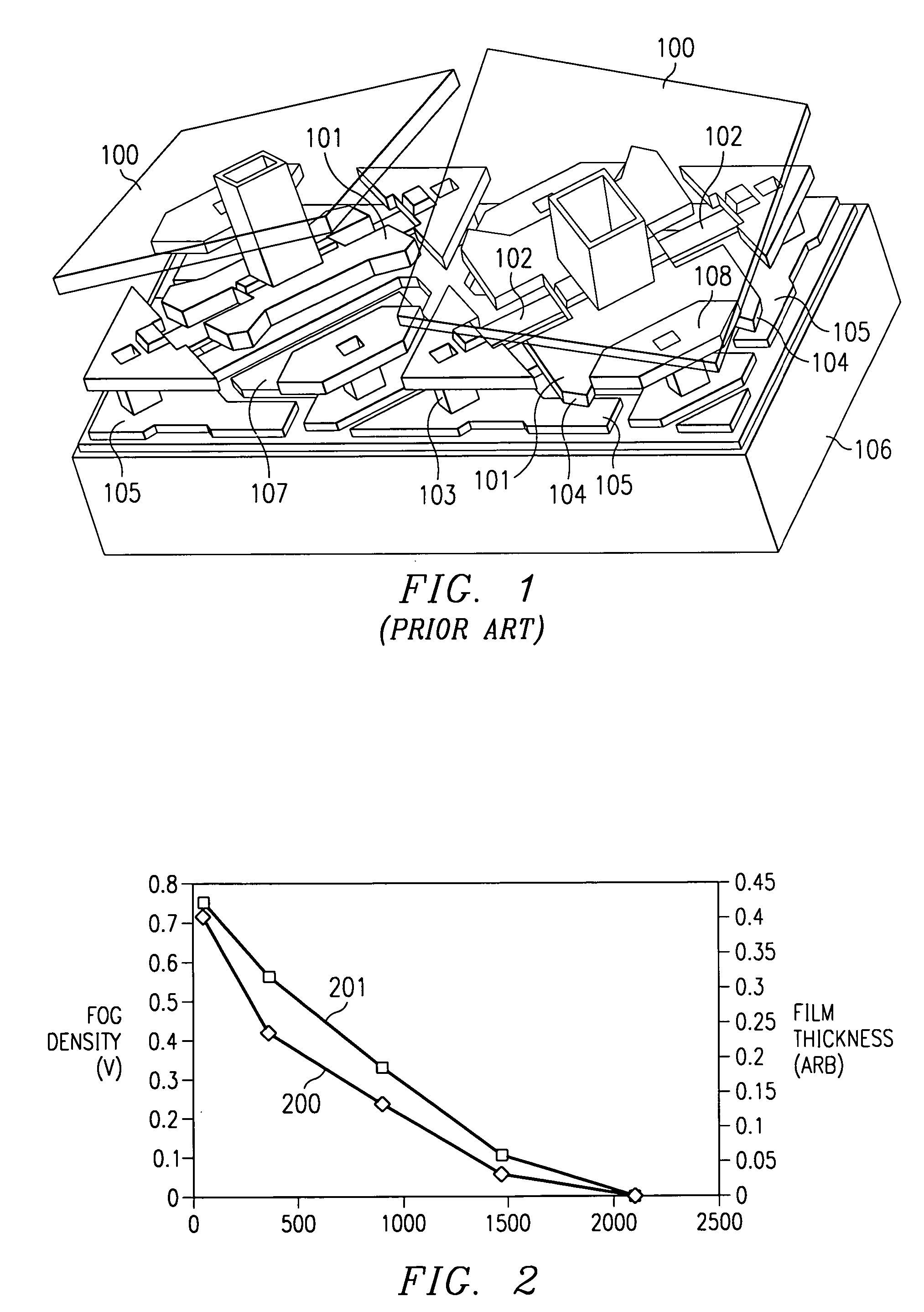
[0022]FIG. 2 shows the results of an experiment performed to determine how the aerosol fog density 200 and thus the deposition rate drop-off with time after charging a chamber with a lubricant and then sealing the chamber. Curve 201 represents the oil film thickness as measured on the surface of a specimen. The results of this experiment indicate that a constant, well controlled, flow of lubricant is required for proper passivation of a MEMS device.

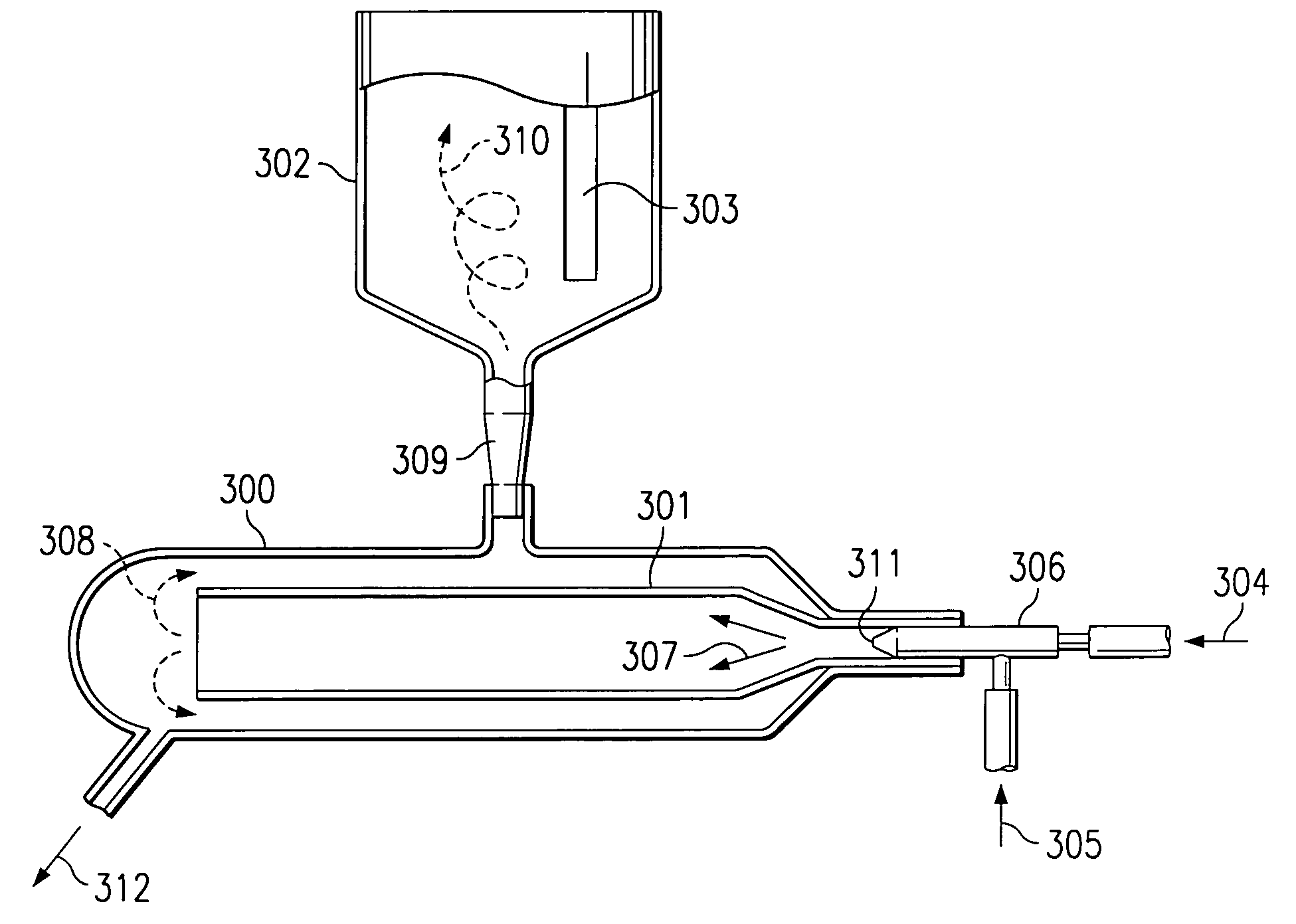
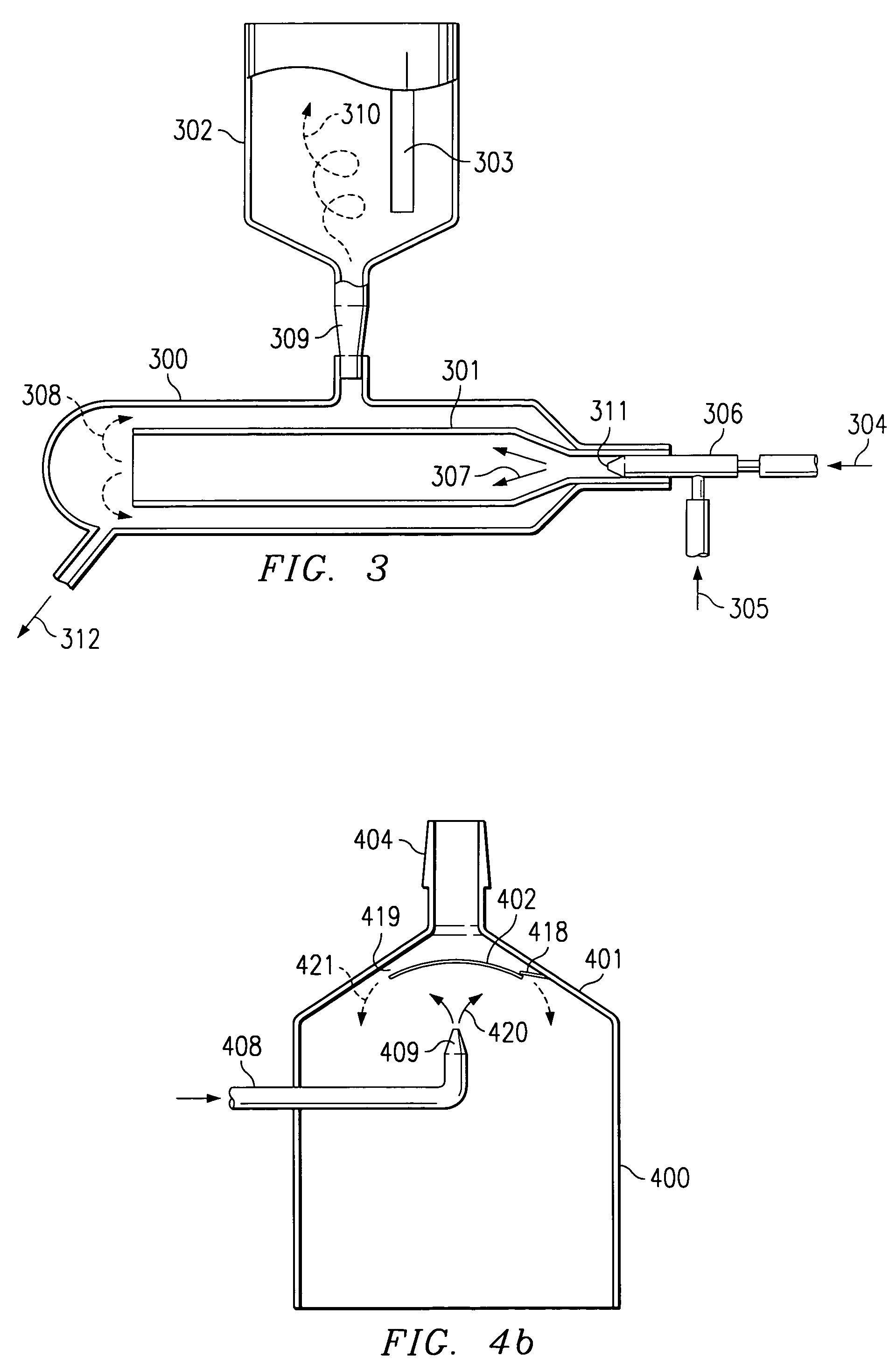
[0023]FIG. 3 is a schematic drawing for the concept nebulizer system of the present invention. The system consist of a lubricant aerosol mixing chamber 300 and a specimen (device) deposition chamber 302 attached to the mixing chamber 300 by means of a neck tube 309. The lubricant 304 is applied to the...


PUM

PropertyMeasurementUnit
passivation timeaaaaaaaaaa
circumferenceaaaaaaaaaa

Abstract

A nebulization system, which creates a uniform fog of tiny suspended liquid droplets, to lubricate the surfaces of MEMS devices. These droplets fall over the edge of a baffle and are then mixed with an umbrella-like sheet of N2 turbulation gas to generate a uniform cloud of droplets that fill a passivation chamber. The MEMS device is then positioned in this uniform cloud of lubricant droplets for a specified amount of time, thereby uniformly lubricating all the surfaces of the device. The system uses a laser monitoring approach to control the uniformity of the lubricant cloud by providing feedback to the system to control the flow of gases. The system also equalizes the pressure around the sample device seal to prevent gases from entering or exiting the chamber and thereby influencing the environment inside the chamber.

Description

FIELD OF THE INVENTION [0001] The present invention relates to the passivation of MEMS devices and more particularly to a method and apparatus for uniformly applying the lubricant to these devices. BACKGROUND OF THE INVENTION [0002] Micro-machined or micro-electro-mechanical systems (MEMS) devices, where there is repeated physical contact between moving parts, require lubrication to prevent the onset of stiction (static friction). This stiction can be strong enough to cause the parts to stick together irreversibly, making the devices inoperable. [0003] For example, in the digital micromirror device (DMD™) of FIG. 1, which is a type of MEMS device, a potential difference between yoke address electrodes 107 and the yoke 101 (and between mirror address electrodes 108 and the mirror 100) cause the mirror / yoke assemblies 100 / 101 to rotate on torsion hinges 102 attached to support posts 103 until the yoke tips 104 contact landing pads 105 located on a lower layer of the device on top of t...

Claims


Application Information

Patent Timeline
Patent Type & Authority Applications(United States)
IPC IPC(8): B81C99/00
CPCB81C1/00944B81C1/00674
Inventor ROBBINS, ROGER A.
Owner TEXAS INSTR INC
Learn More