Spread spectrum type clock generation circuit for improving frequency modulation efficiency

a clock generation circuit and frequency modulation efficiency technology, applied in the direction of angle demodulation by phase difference detection, automatic control of pulses, electrical devices, etc., can solve the problems of ic using the output clock being erroneously operated, the frequency of the output clock greatly swinging, and the jitter is increased, so as to achieve the effect of improving the frequency modulation efficiency of the output clock and effectively removing the high-frequency noise generated by the modulator

Active Publication Date: 2005-08-18
SEIKO NPC
View PDF9 Cites 18 Cited by
  • Summary
  • Abstract
  • Description
  • Claims
  • Application Information

AI Technical Summary

Benefits of technology

[0017] It is desirable that the loop filter has a series connection of a first capacitance and a resistance to a power supply voltage or ground and a second capacitance connected in parallel with the series connection, and it is desirable that the second capacitance has a value which is not less than one-tenth the first capacitance. By such a configuration, high-frequency noise generated by the ΔΣ modulator can be effectively removed.
[0018] According to the present invention, the peak of the modulation pattern of a modulation digital signal generated in the clock modulation circuit is distributed, thereby allowing the frequency modulation efficiency of the output clock to be improved.

Problems solved by technology

When the amplitude is increased, however, the frequency of the output clock greatly swings, so that jitter is increased.
When the jitter is too high, an IC using the output clock may be erroneously operated.
Therefore, a method of increasing the amplitude of the modulation waveform to improve the modulation efficiency has a limit.
Therefore, the modulation waveform is frequently distorted.
Since the slope of the triangular waveform is constant, however, the triangular waveform is inferior in frequency modulation efficiency.

Method used


Image

  • Spread spectrum type clock generation circuit for improving frequency modulation efficiency
  • Spread spectrum type clock generation circuit for improving frequency modulation efficiency
  • Spread spectrum type clock generation circuit for improving frequency modulation efficiency

Examples


Embodiment Construction

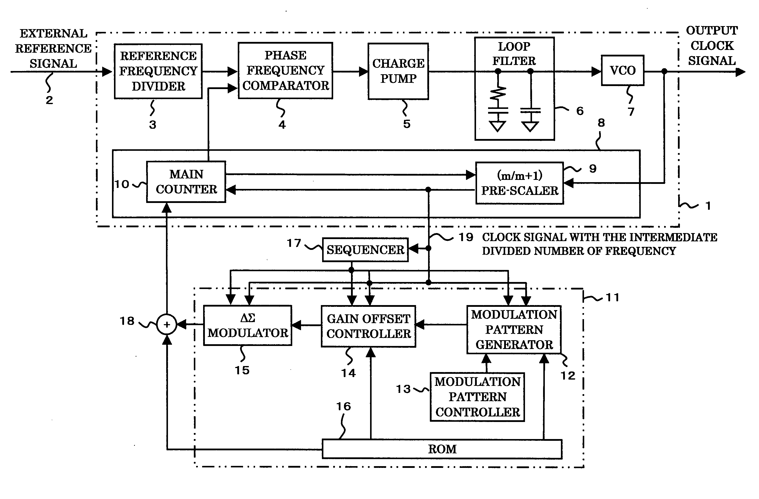
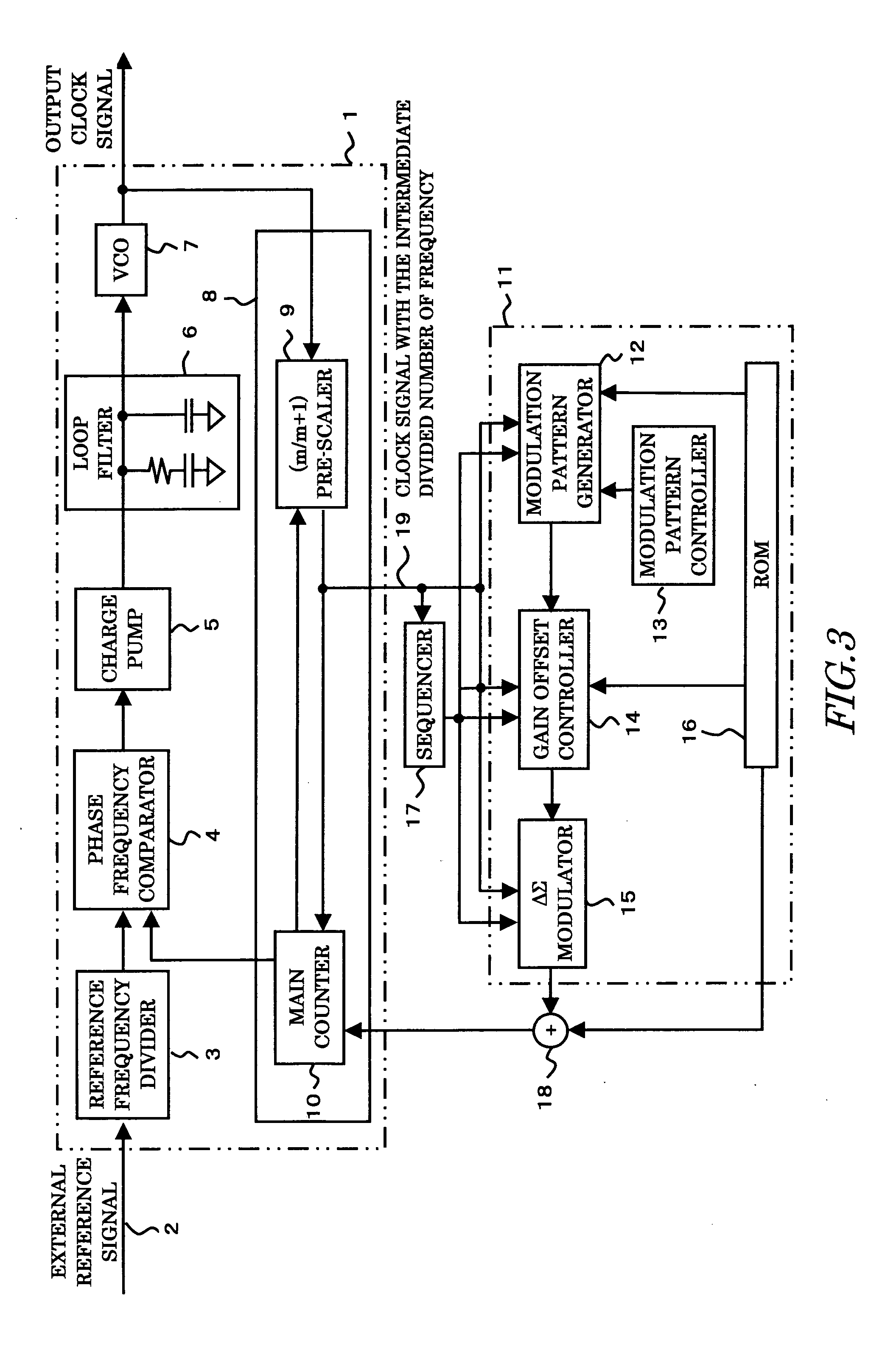
[0029] A suitable embodiment of the present invention will be described on the basis of the accompanying drawings. FIG. 3 is an explanatory view showing an example of a clock generation circuit according to the present invention. In FIG. 3, reference numeral 1 denotes a phase-locked loop circuit, and reference numeral 11 denotes a clock modulation circuit for generating a signal for clock modulation.

[0030] The phase-locked loop circuit 1 comprises the following constituent elements. Reference numeral 2 denotes an external reference signal. The external reference signal 2 is frequency-divided into a predetermined comparison frequency by a reference frequency divider 3. A phase frequency comparator 4 compares the phases of an output of the reference frequency divider 3 and an output of a frequency divider 8, described later, to generate an phase error signal. A charge pump 5 receives an output of the phase frequency comparator 4, to generate a charge amount corresponding to the phase...


PUM


Abstract

The present invention provides a spread spectrum type clock generation circuit whose EMI for peripheral equipment is reduced. The clock generation circuit comprises a phase-locked loop circuit and a clock modulation circuit. The clock modulation circuit comprises a ΔΣ modulator, to frequency-modulate an output clock by modulating the frequency division number of a frequency divider in the phase-locked loop circuit by a digital circuit, and further comprises a modulation pattern controller for distributing the peak of a triangular waveform which is a modulation waveform generated by a modulation pattern generator to change the amplitude and the period thereof, thereby making it possible to eliminate dullness and distortion of a modulation waveform in a modulating method using a conventional analog circuit and to obtain an output clock having higher modulation efficiency than that in a case where a normal triangular waveform is employed in a conventional modulating method using a digital circuit.

Description

BACKGROUND OF THE INVENTION [0001] 1. Field of the Invention [0002] The present invention relates to a clock generation circuit for frequency-modulating an output clock, and more particularly, to a Spread Spectrum type clock generation circuit whose electromagnetic interference (hereinafter referred to as EMI) for peripheral equipment is reduced. [0003] 2. Related Background Art [0004] Conventionally, as EMI measures, a clock generator having a clock modulation circuit may be employed in many cases in order to reduce the number of components such as ferrite beads and a passive filter in a case where the frequency of a system operation clock exceeds 10 MHz. However, the higher frequency modulation efficiency is in the clock generator, the more effective the use of the clock generator is as the EMI measures. [0005] In a case where frequency modulation is performed with respect to a general clock generation circuit, modulation efficiency in the frequency modulation indicates how much t...

Claims


Application Information

Patent Timeline
Patent Type & Authority Applications(United States)
IPC IPC(8): H03L7/183H03K7/08H03L7/197
CPCH03L7/197
Inventor HATTORI, YUJI
Owner SEIKO NPC
Why Eureka
Try Eureka