Imaging scope

a fiber optic and scope technology, applied in the field of fiber optic imaging scopes, can solve the problem of only being able to achieve the degree of precision, and achieve the effects of reducing costs, avoiding breakage, and high-precision optical, mechanical, ergonomical and physical characteristics

Inactive Publication Date: 2005-08-18
UNIV OF FLORIDA RES FOUNDATION INC
View PDF73 Cites 183 Cited by
  • Summary
  • Abstract
  • Description
  • Claims
  • Application Information

AI Technical Summary

Benefits of technology

[0012] The subject invention pertains to a system for imaging the human airway having highly advantageous optical, mechanical, ergonomical and physical characteristics. The subject system allows for a user to utilize conventional techniques for the insertion of an endotracheal tube while using the subject imaging scope. The excellent characteristics of the imaging system of the subject invention result, in part, from the use of plastic optical fibers. Plastic optical fibers are more robust than the glass optical fibers used in currently available imaging systems, and are therefore capable of being bent and / or twisted with virtually no concern of breakage. In addition, the lower costs of plastic optical fibers enables scopes of the subject invention, in a specific embodiment, to be manufactured for single patient use thereby eliminating the requirement for cleaning, special care, the maintenance of expensive inventory, and most importantly eliminating the opportunity for cross contamination between patients. A further aspect of the subject invention concerns a novel sheath which can cover all or a portion of the parts of the imaging system which enter the patient. This sheath can reduce the need for expensive sterilization of the subject intubation scope after use.
[0013] An embodiment of the subject imaging system utilizing plastic optical fiber is highly advantageous because of its longer life, increased ruggedness, greater flexibility, comparable image quality, optional disposability, and lower cost, compared to glass scopes. These scopes are useful, for example, for observing the bronchi of the lungs, locating the tracheal opening to allow insertion of an endotracheal tube into the trachea for intubation, and visually locating the endotracheal tube tip. Specifically, using a scope of the subject invention, a practitioner can easily and precisely identify the exact location of the distal end of the tracheal tube, as well as the various anatomical airway landmarks. Currently, this degree of precision is only possible with an expensive glass fiberoptic bronchoscope. In addition, the scopes of this invention are particularly advantageous for use in anesthesiology.
[0014] In a specific embodiment, the subject imaging system can incorporate a malleable stylet which can retain its shape when bent. This embodiment can be used as an intubation scope. During an intubation, an anesthesiologist can insert the subject intubation scope into an endotracheal tube to be inserted into a patient. Once the intubation scope is inserted into the endotracheal tube, the anesthesiologist can bend the intubation scope - endotracheal tube combination into a shape, essentially any shape, which facilitates insertion into the patient. Advantageously, the anesthesiologist can then hold the scope-tube combination in one hand, with a conventional grip, for example in a pen-like fashion, and easily maneuver the scope-tube combination during insertion into the patient. This is facilitated as a result of the center of balance of the scope / stylet-tube combination being in approximately the center ⅓ of the length of the scope / stylet-tube combination.
[0016] In a specific embodiment, the subject invention pertains to a plastic optical fiber imaging scope, having an optional sheath, for intubation. This intubation scope can be used for intubation of patients under general and / or local anesthesia. The intubation scope of this embodiment can be disposable, sterilizable for reuse, or enclosed within a disposable sheath for reuse without expensive sterilization. Due to lower cost for the plastic optical fiber scopes, the scopes of the subject invention are particularly advantageous for situations calling for disposable scopes, and can be less expensive than the cleaning and sterilization costs for existing glass scopes.

Problems solved by technology

Currently, this degree of precision is only possible with an expensive glass fiberoptic bronchoscope.

Method used


Image

  • Imaging scope
  • Imaging scope
  • Imaging scope

Examples


example 1

[0071] The device of the subject invention not only makes intubation easier and more accurate, but also reduces the potential for inflicting injury with the laryngoscope blade. Using the device of the subject invention, the practitioner only needs to use the laryngoscope blade to control the position of the patient's tongue. The device can also be used without a laryngoscope and for nasotracheal intubation.

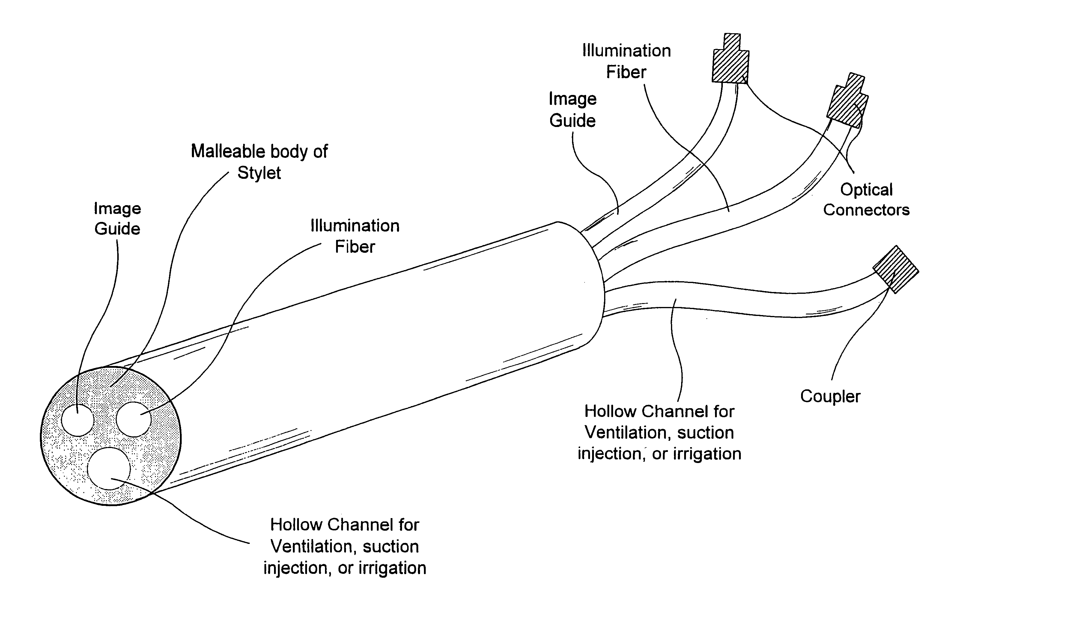
[0072] The device of the subject invention can comprise a bundle of 10,000 individual plastic optical fibers (bundle is approximately 1.0 millimeter in diameter). The resolution of the image is comparable to an existing glass fiberoptic bronchoscope, providing good visualization of the patient's airway.

[0073] The manufacturing process places the bundle integral to a standard malleable stylet. An additional fiber may be used for illuminating purposes. Suctioning and insufflation can be added by adding an additional channel if desired.

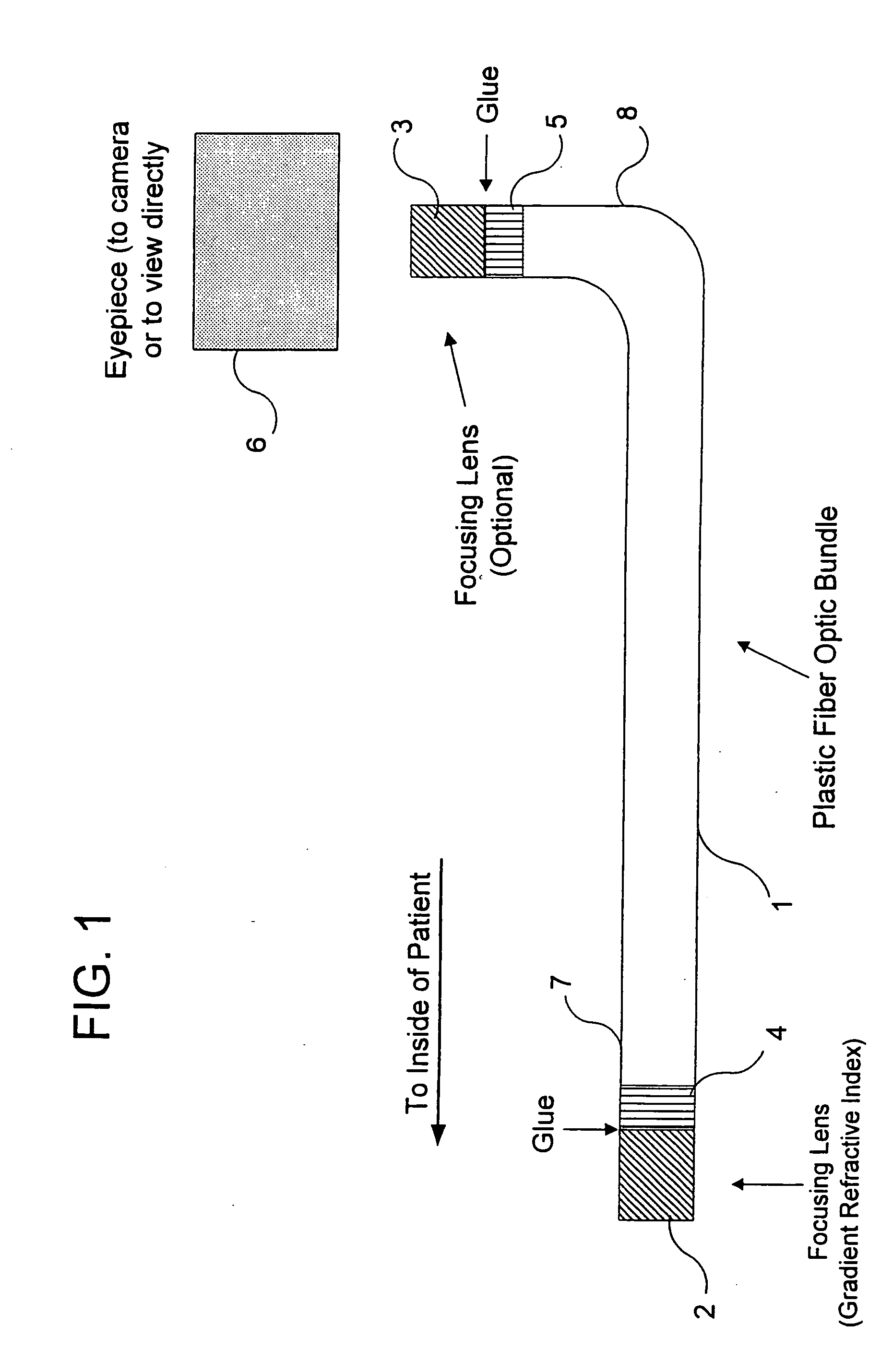
[0074] A focusing lens (i.e., gradient refrac...

example 2

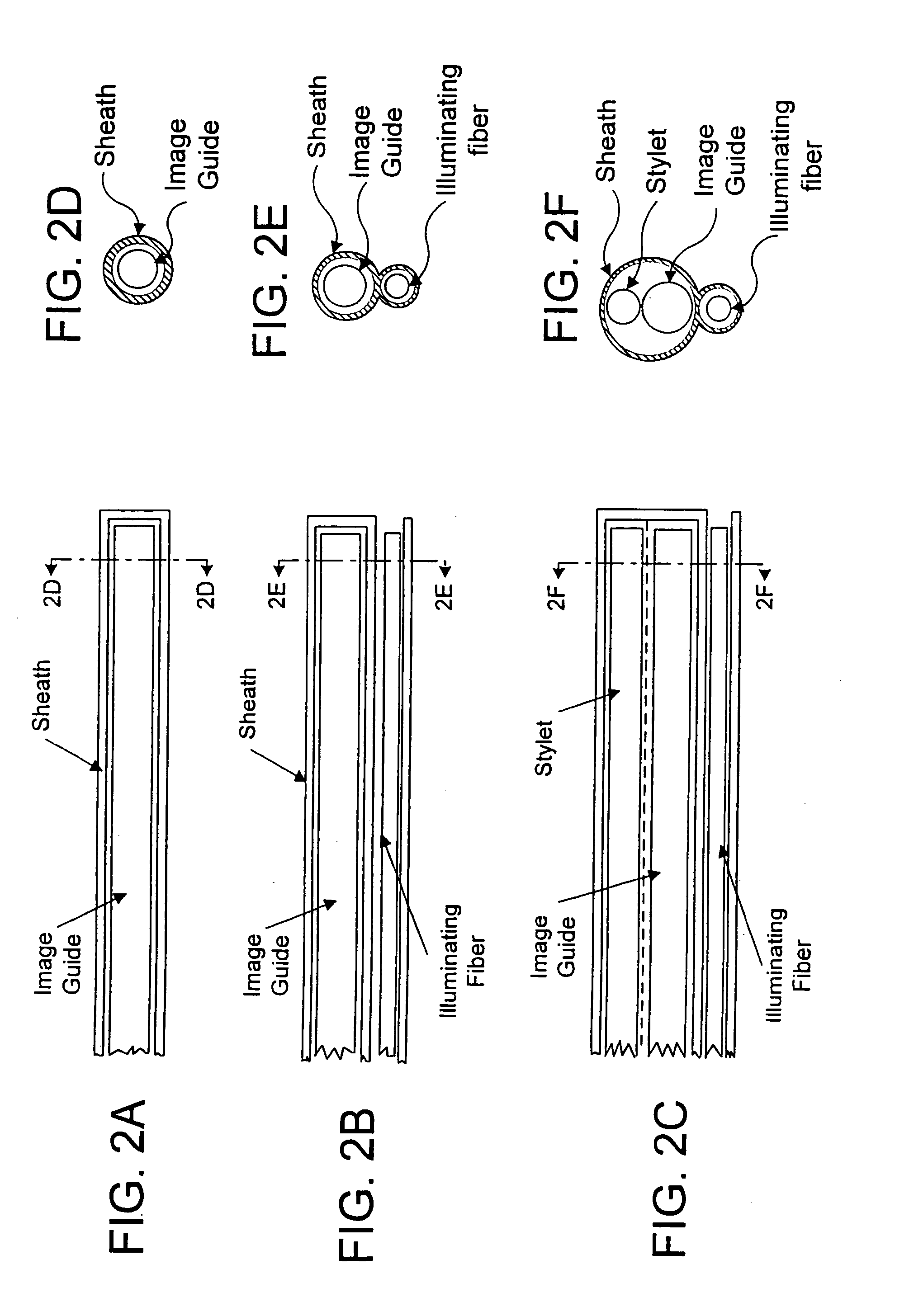
[0075] Referring to FIGS. 2A, 2B, 2C, 2D, 2E, and 2F, this example provides three illustrative combinations of image guide, illuminating fiber, stylet, and / or sheath. FIGS. 2A and 2D illustrate a longitudinal cross section and a transverse cross section, respectively, of the distal end of a sheath designed to fit over a plastic optical fiber image guide. The sheath covers the distal tip of the image guide with a transparent end plate. In this case, any illuminating fibers and / or stylets would not be enclosed within this sheath, although they could have their own sheaths.

[0076]FIG. 2B and 2E illustrate a longitudinal cross section and a transverse cross section, respectively, of the distal end of a sheath designed to fit over a plastic optical fiber image guide, wherein the sheath comprises an illumination fiber. The distal end of the illumination fiber is not covered by the sheath, in this example, so as to not impair the image. Accordingly, the illuminating fiber can be disposed o...

example 3

[0078] It is sometimes necessary to replace an endotracheal tube in a patient, for example when the tube no longer provides an adequate airway. In a specific embodiment, the subject invention can permit the easy removal of one endotracheal tube and its replacement with a new one.

[0079] A device in accordance with the subject invention can be inserted into the patient's trachea, generally through an existing tracheal tube, until the distal tip is at or near the tip of the tube. Oxygen for ventilation, suction or irrigation can also be applied in succession via, for example, quick fit connectors to the proximal end if desired. Once the anatomy is visualized, the light source, camera or eyepiece, and oxygen / suction / irrigation can all be disconnected from the proximal end of the subject device. The endotracheal tube can then be completely removed by sliding it out of the trachea, along, and off the proximal end of the subject device. The connectors of the subject device can be of a sui...


PUM


Abstract

Disclosed is an intubation imaging stylet for intubating a patient by use in a tube / imaging stylet combination, said imaging stylet comprising: a malleable stylet having a longitudinal axis and a proximal end and a distal end; a flexible image guide having a longitudinal axis and a proximal end and a distal end, said image guide being connected to said stylet such that a portion of said image guide runs parallel to a portion of said stylet along the longitudinal axis of said stylet and such that the distal end of said image guide is co-extensive with the distal end of said stylet; and at least one flexible illumination fiber having a proximal end and a distal end, said illumination fiber being connected to said stylet such that a portion of said illumination fiber runs parallel to a portion of said stylet along the longitudinal axis of said stylet and such that the distal end of said illumination fiber is co-extensive with the distal end of said stylet; such that in use, said imaging stylet is disposed within a tube for intubating a patient thereby forming an imaging stylet / tube combination which in use is held by gripping the tube in a pen-like fashion. The imaging stylet / tube combination is thus in use held in one hand, freeing the other hand of the user for other tasks if necessary, as well as permitting intubation in the conventional manner. To facilitate this, the center of gravity of the imaging stylet / tube combination is located in essentially the same location along the tube as with a conventional stylet / tube combination.

Description

CROSS-REFERENCE TO RELATED APPLICATION [0001] This application is a continuation-in-part of co-pending patent application Ser. No. 10 / 807,965, filed Mar.24, 2004, which is a continuation-in-part of Ser. No. 10 / 001,560, filed Oct. 23, 2001, now abandoned, which is a continuation of patent application Ser. No. 09 / 007,939, filed Jan. 16, 1998 (now U.S. Pat. No. 6,322,498; issued Nov. 27, 2001) which is a continuation-in-part of international patent application Ser. No. PCT / US97 / 17954, filed Oct. 6, 1997; which is a continuation of patent application Ser. No. 08 / 725,779 filed Oct. 4, 1996 (now U.S. Pat. No. 6,115,523; issued Sep. 5, 2000).BACKGROUND OF THE INVENTION [0002] This invention relates to fiber optic imaging scopes and, in a particular embodiment, to intubation scopes. The subject intubation scopes can incorporate a malleable stylet, which can retain its shape when bent, to facilitate intubation. Advantageously, this invention can utilize plastic optical fibers to enhance the ...

Claims


Application Information

Patent Timeline
Patent Type & Authority Applications(United States)
IPC IPC(8): A61B1/04A61B1/267A61M16/04
CPCA61B1/0017A61B1/042A61B1/07A61B5/064A61B1/00167A61B1/2676
Inventor GRAVENSTEIN, DIETRICHLAMPOTANG, SAMSUNMELKER, RICHARD J.
Owner UNIV OF FLORIDA RES FOUNDATION INC
Why Eureka
Try Eureka