Hydrogen storage and supply system

a hydrogen storage and supply system technology, applied in the direction of containers, instruments, packaging goods, etc., can solve the problems of very effective hydrogen diffusion, current paucity of fully satisfactory systems, and effective prevention of such diffusion, and achieve the effect of high surface area

Inactive Publication Date: 2005-08-25
NANOMIX
View PDF7 Cites 10 Cited by
  • Summary
  • Abstract
  • Description
  • Claims
  • Application Information

AI Technical Summary

Benefits of technology

[0010] In accordance with an embodiment of the present invention a cryosorptive hydrogen storage system that includes a hydrogen source apparatus and a cryosorptive hydrogen storage apparatus is provided. The medium that stores the hydrogen is porous and has high surface area. In some embodiments,...

Problems solved by technology

A number of technological components present challenges in making this transition to a hydrogen economy, and in the development of appropriate systems and infrastructure that can integrate into those that already exist.
Particularly in the automotive industry, one significant challenge involves the current paucity of fully satisfactory systems for hydrogen storage, ones that are safe, reliable, conformable, light-weight, and comprehensively economic.
The technical issues underlying various approaches to hydrogen storage include the form within which hydrogen is stored, the nature of the medium holding the hydrogen, and the operation of the containers holding the medium.
A problem with this method is that hydrogen diffuses very effectively, particularly when under high pressure, and currently available high pressure tanks do not effectively prevent such diffusion over an extended period of time.
The requirement that tank materials be lightweight, and the fact that tank failure or damage in the event of an accident would be catastrophic provides further reason for pause.
However, liquid hydrogen storage is burdened with a high boil-off ...

Method used


Image

  • Hydrogen storage and supply system
  • Hydrogen storage and supply system
  • Hydrogen storage and supply system

Examples


Embodiment Construction

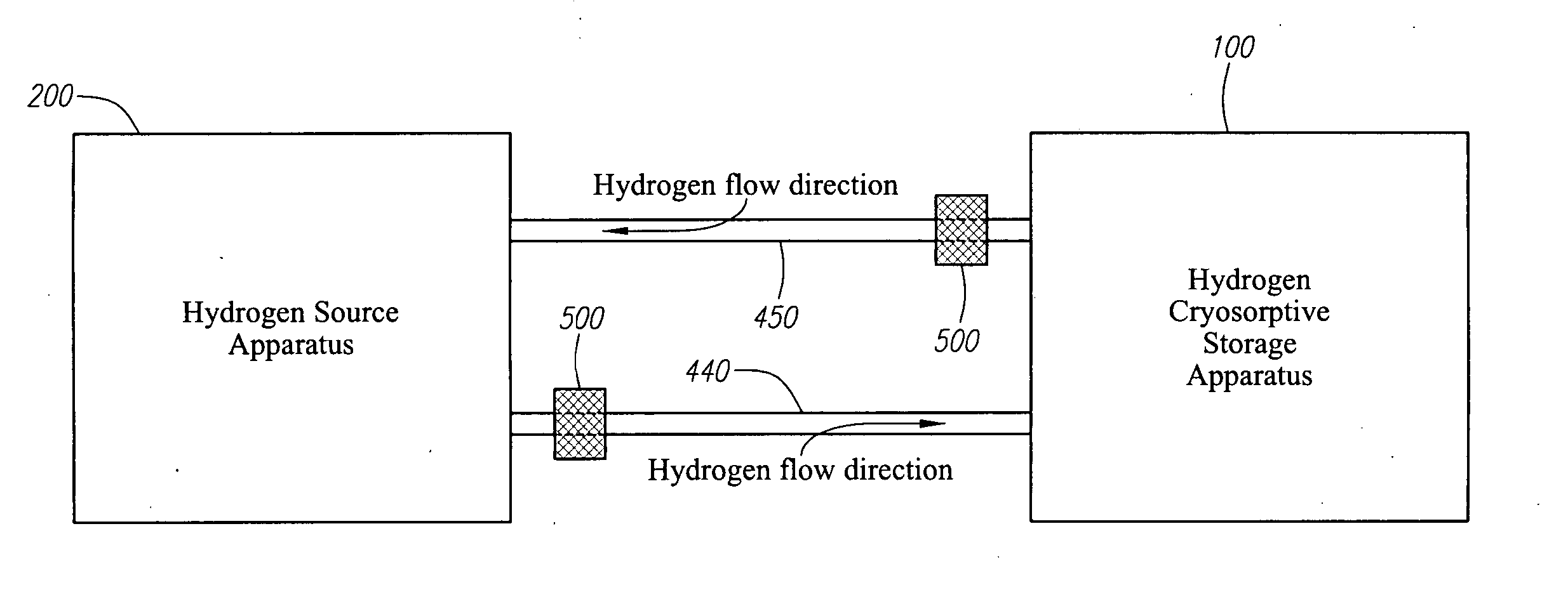
The Cryosorptive Storage System: Features and General Operating Considerations

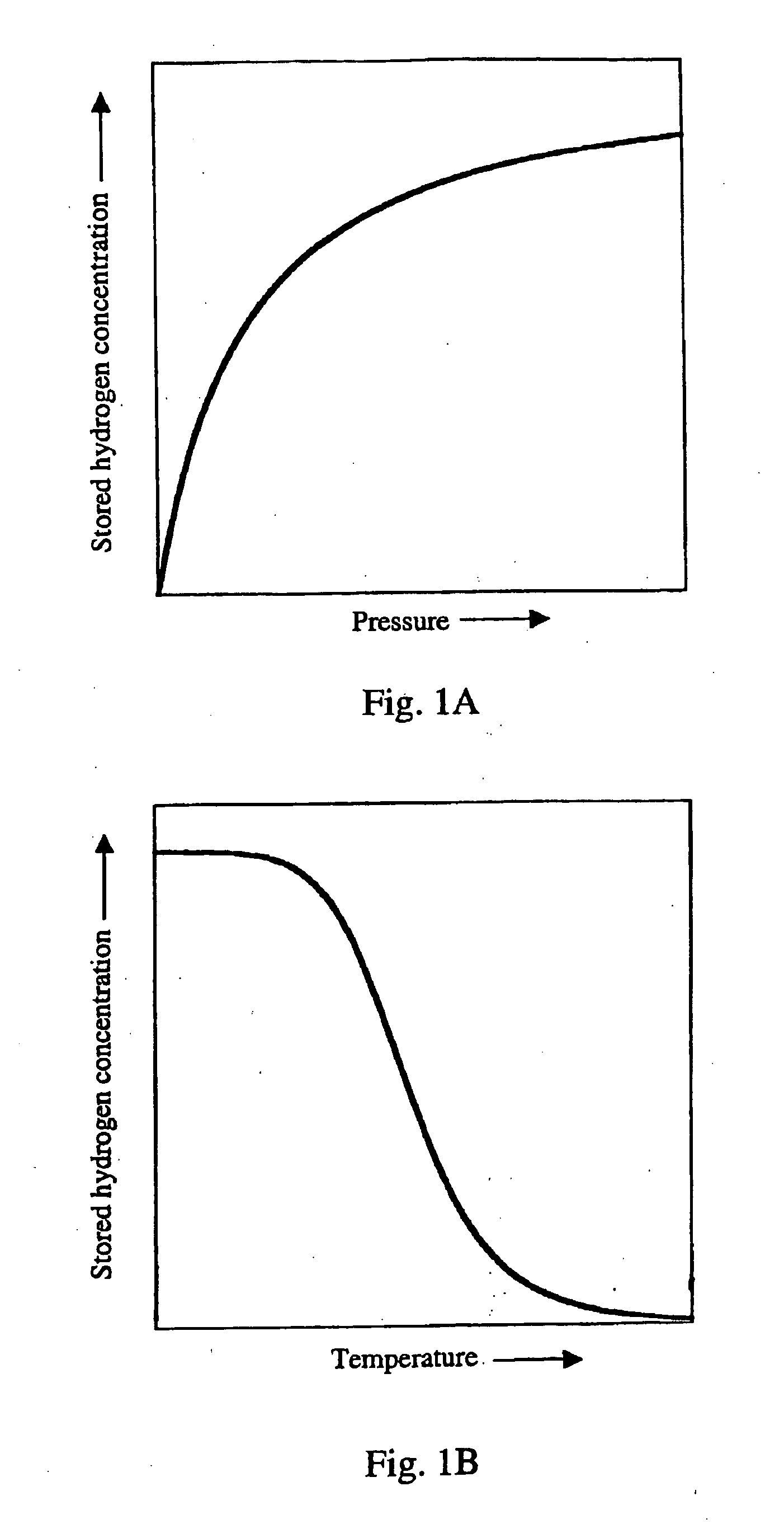
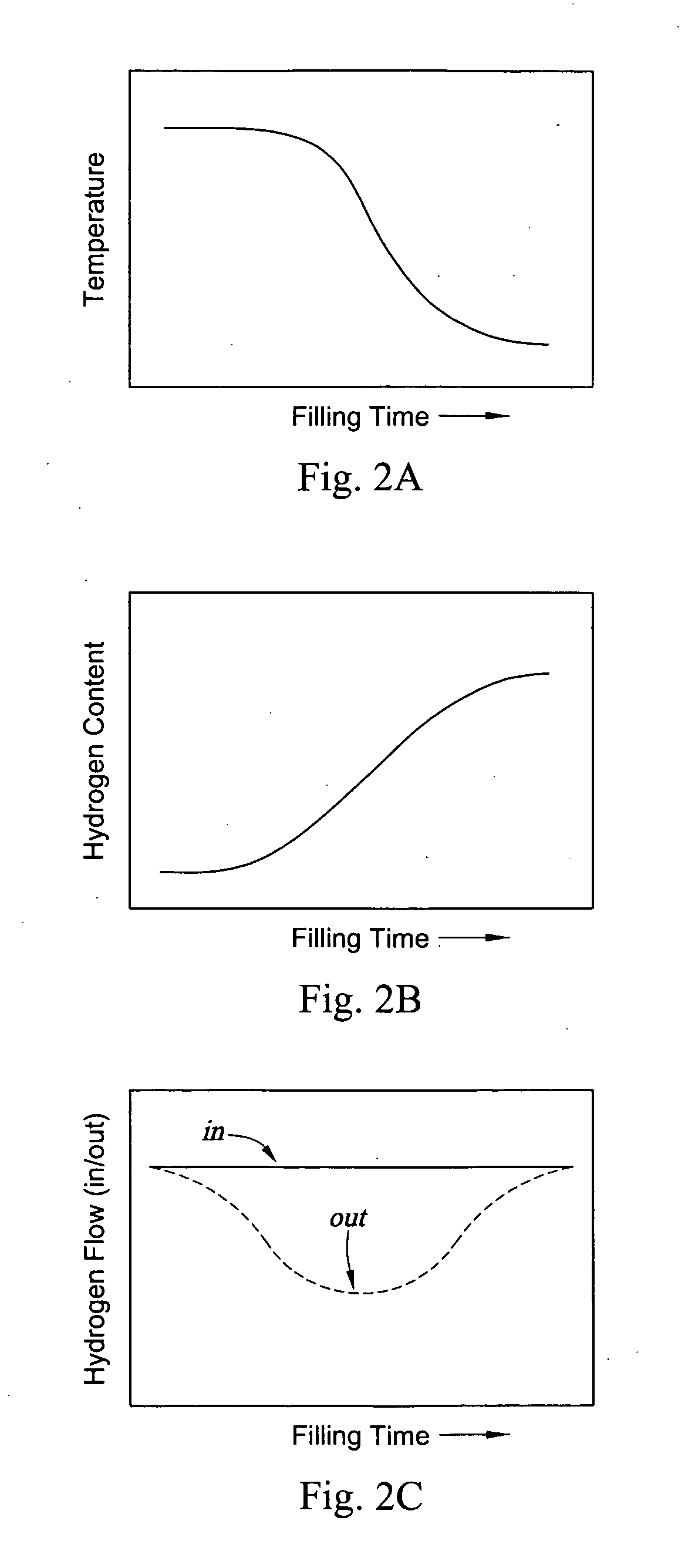
[0027] By adsorbing hydrogen on a high surface area medium at cryogenic temperatures, hydrogen can be stored densely at low pressures. Two areas of technology development will contribute to this area of commercial development and application. First, hydrogen storage media should be improved in terms of binding energy, storage capacity, and overall density. The first commercially practical porous hydrogen storage medium is likely to be either modified carbon, or boron nitrides, or new high-binding-energy media. Applicant has recently submitted a U.S. patent application (Jhi et al., Boron Oxide and Related Compounds for Hydrogen Storage), which provides an example of such a hydrogen storage medium. A second important area of technology development involves the engineering of effective containers and surrounding operating systems to accommodate and enable this form of hydrogen storage. In general, container...


PUM

PropertyMeasurementUnit
Specific surface areaaaaaaaaaaa
Flow rateaaaaaaaaaa
Surface areaaaaaaaaaaa

Abstract

This invention provides for an apparatus and a method for operation of a cryogenic hydrogen storage system that contains a porous medium configured to adsorb hydrogen. The hydrogen storage and supply system includes a hydrogen source apparatus and a cryosorptive storage apparatus. Methods and devices that allow for an energy efficient filling of the cryosorptive apparatus from the hydrogen source apparatus are described. The cryosorptive hydrogen storage apparatus is filled with cold, pressurized hydrogen. During the course of filling, heat is generated in the cryosorptive storage device by the process of hydrogen adsorption on to the host medium. Methods and devices are provided for the removal the generated heat and the warm hydrogen. Further provided are devices and methods for the capture and recycle of escaped hydrogen within the hydrogen source apparatus.

Description

DOMESTIC PRIORITY CLAIM [0001] The priority of U.S. Provisional Application No. 60 / 406,787, filed Aug. 29, 2002, is claimed.FIELD OF THE INVENTION [0002] This invention relates generally to the storage of hydrogen in containers and, more specifically, to an apparatus and a method for operation a cryogenic hydrogen storage system that contains porous media that can adsorb or absorb hydrogen. BACKGROUND OF THE INVENTION [0003] There is considerable interest in replacing fossil fuels with hydrogen because of hydrogen's high energy density per unit weight, its readily availability through the electrolysis of water, and the absence of polluting byproducts from its use. A number of technological components present challenges in making this transition to a hydrogen economy, and in the development of appropriate systems and infrastructure that can integrate into those that already exist. Particularly in the automotive industry, one significant challenge involves the current paucity of fully...

Claims


Application Information

Patent Timeline
IPC IPC(8): B65B1/04B65B1/30B65B3/04B65B3/26B67C3/02B67D99/00F17C11/00F17C13/02G06F17/00
CPCF17C11/005Y02E60/321G06Q50/06Y02E60/32Y02P90/45
Inventor BRADLEY, KEITHWYATT, JEFFJHI, SEUNG-HOONKWON, YOUNG-KYUNGABRIEL, JEAN-CHRISTOPHEGRUNER, GEORGE
Owner NANOMIX
Why Eureka
Try Eureka