FIB-SEM complex apparatus

Active Publication Date: 2005-08-25
HITACHI HIGH TECH SCI CORP
View PDF1 Cites 57 Cited by
  • Summary
  • Abstract
  • Description
  • Claims
  • Application Information

AI Technical Summary

Benefits of technology

[0013] The invention is the complex apparatus including an FIB lens-barrel and an SEM lens-barrel, in which the slit of a machining shape is provided in the aperture for FIB, whereby ion beam machining is performed by transferring a pattern onto a sample surface rather than scanning by a focused ion beam. Thus, an FIB noise superimposed on an SEM detection signal changes to a background noise uniform for a machining area and never disturbs an image.
[0014] In addition, the complex apparatus including an FIB lens-barrel and an SEM lens-barrel of the invention includes slits of plural machining pattern shapes and a switching unit for switching the plural machining patterns in the aperture for FIB to thereby make it possible to perform various kinds of machining by selecting or combining the machining patterns without replacing and attaching a slit.
[0015] The ion beam machining method of the invention using a complex apparatus including an FIB lens-barrel, which has an aperture with a slit formed in a machining shape, and an SEM lens-barrel includes: a step of detecting a machining position according to an SIM image of focused ion beam scanning; a step of switching an ion optical system from a focusing mode to a transfer mode; and a step of transferring a pattern of the slit to the detected, machining position and machining the pattern. Thus, it is possible to execute a series of work including the detection of a position, the mode switching by the ion optical

Problems solved by technology

However, in this case, work of machining and observing a state of the machining has to be carried out repeatedly.
For example, a section machining observation apparatus described in JP-A-2-123749 has an object of solving problems in that operation is troublesome because the apparatus has to be moved between a machining angle (usually, horizontal) and an observation angle (about 45 to60 degrees) several times, mechani

Method used


Image

  • FIB-SEM complex apparatus
  • FIB-SEM complex apparatus
  • FIB-SEM complex apparatus

Examples


first embodiment

[First Embodiment]

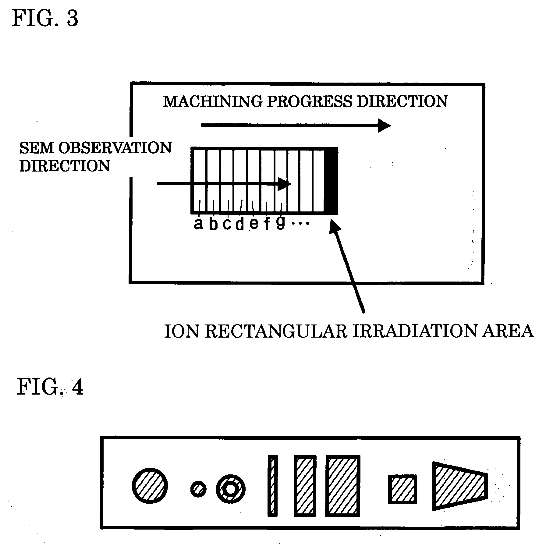
[0036]FIG. 4 shows an embodiment of an aperture that is used in the complex apparatus of the invention. In the embodiment shown here, opening patterns are a large circle, a small circle, a ring, rectangles with small, medium, and large widths, a square, and a trapezoid. It is needless to mention that patterns are not limited to these and can be created appropriately. In use, when a pattern matches a machining area, the pattern only has to be selected and used. Alternatively, it is also possible to combine several patterns to create a necessary machining pattern. In the latter case, patterns to be combined only have to be selected in order to carry out machining. All the cases are the same in that an area is uniformly irradiated by an FIB rather than scanning the area with the FIB to form a machining pattern. Thus, the FIB simply becomes a uniform background noise for an SEM signal in the machining area,

second embodiment

[Second Embodiment]

[0037] Next, FIG. 5 shows an embodiment including means for removing a uniform background noise due to ion beam irradiation from an SEM signal in which the background noise is detected. In view of the fact that this background noise is superimposed on the SEM signal as a bias component corresponding to a beam current of an FIB, the inventors has reached an idea of detecting the beam current of the FIB and correct the beam current. For this beam current detection, it is advantageous to arrange the aperture 5 of a transfer pattern determining a machining are a between the object lens OL and a sample surface in a mask form. By forming this mask with a conductive material, it is possible to use the aperture 5 also as a beam current detector. In other words, as shown in FIG. 5, the aperture 5 arranged in the mask form between the object lens OL, which is arranged on a tip side of the FIB lens-barrel 1, and the sample surface is used as a detection electrode to pick up ...

third embodiment

[Third Embodiment]

[0039] Next, FIG. 7 shows another embodiment including means for removing a uniform background noise due to ion beam irradiation from an SEM signal in which the background noise is detected. In the embodiment described above, a beam current of an FIB, which causes this background noise, is detected and corrected. However, in this embodiment, in view of the fact that a beam current of an FIB is measured in advance and can be allocated to setting conditions for a lens optical system of an FIB apparatus, the inventors has reached an idea of performing level adjustment based on the setting conditions for the lens optical system without measuring a beam current directly. As shown in FIG. 7, in this embodiment, it is unnecessary to provide a special component. A beam current is calculated from the setting conditions for the lens optical system in a controller and a background noise level based on this beam current is further calculated to perform correction for the backg...


PUM


Abstract

In a complex apparatus including an FIB lens-barrel and an SEM lens-barrel, a slit of a desired shape is provided as an aperture for FIB, an ion beam of a beam width covering the slit is irradiated on a sample surface to transfer a pattern of the slit onto the sample surface to thereby perform ion beam machining.

Description

BACKGROUND OF THE INVENTION [0001] The present invention relates to a complex apparatus that can observe a sample with a scanning electron microscope (SEM) on a real time basis while machining the sample with a focused ion beam apparatus (FIB). [0002] There has already been publicly known a so-called complex FIB system that is provided with an electron lens-barrel separately to have an observation function by an SEM in order to observe a machining state of a sample in applying etching and CVD to the sample with an FIB apparatus. In addition to functions for performing the etching and the CVD, the FIB apparatus includes a function as an ion microscope for detecting a secondary charged particle such as an electron or an ion emitted from a sample surface by ion irradiation and forming an amount of the detection as an image in association with an irradiation position. In response to needs for an observation of a sectional structure at a desired point of a semiconductor wafer, an LSI dev...

Claims


Application Information

Patent Timeline
IPC IPC(8): H01J37/28H01J37/305H01J37/317H01L21/66
CPCH01J37/28H01L22/26H01J2237/31749H01J37/3056
Inventor OI, MASAMICHIOGAWA, TAKASHI
Owner HITACHI HIGH TECH SCI CORP
Why Eureka
Try Eureka